|
|
|
[Sponsors] | ||||
 September 12, 2009, 18:38
|
|
#1 |
|
New Member
Matt
Join Date: Sep 2009
Posts: 12
Rep Power: 16  |
Hi, I'm a new user to Ansys and ICEM and i seem to be having trouble understanding how to make an unstructured 2d mesh. I am mapping an airfoil with some convex corners and would like to utilize a tet mesh to accomplish this. Through trial and error and the ICEM 11 tutorial i discovered that a tet mesh can only be generated on a surface. To approach my problem i created a rectangular "background" curve with the airfoil as another curve in the center of it. I then created a surface from my background and segmented this surface at the airfoil curve. Then i deleted the surface representing the airfoil. This left me with a single rectangular surface with my airfoil shaped hole in it. I was pretty easily able to then define mesh parameters and create an all tri mesh on this surface. For reference i do have the int wall option selected in part setup.
Where i run into problems is in defining the boundary conditions for my solver which is Fluent. When in my family boundary conditions window i would like to just be able to specify like the left, top, and bottom of the box as velocity inlets and the right as an outlet. Additionally i would want to specify the hole in the surface that is my airfoil as a no slip wall. I don't know if i should define from the Mixed/Unknown drop down or from the edges drop down. In the tutorials a 2d problem was never solved but within a 3d problem boundary conditions were always specified on a surface. I don't think this would work for me as all i have is a surface and some other random curves from building the geometry. Ideally i would like to just be able to select the left side of my surface and make it velocity inlet. I doubt its going to be that easy though. If any one could give me a few pointers on how to proceed. Maybe i used the wrong approach by creating a surface to tet mesh from the beginning or maybe i'm just missing a key step. I have included some pictures of what i'm working with below. Thanks!   
|
|

|

|
|
|
September 13, 2009, 07:18
|
|
#2 |
|
Member
Jules Bell
Join Date: May 2009
Posts: 32
Rep Power: 16 |
... all I know is CFX so what I'm telling you might be completely wrong. (Anyone who knows better than I correct me please)
This is general ICEM (should be true for you anyway): You can create "parts" in ICEM and assings individual geometry elements to these parts. You can also associate mesh elements to parts, in your 2D case this would be the line elements that lie on the bounding curves. (If you created your surface mesh from curves and defined the spacings on each curve, the line elements should already be associated to these curves and the respective parts) Note that for CFX you must have a 3D mesh with uniform 1-cell thickness for analyzing 2D problams, I don't know about fluent. This means for CFX you would extrude your mesh and associate the surface elements that were created on the boundaries by extrusion to geometry surface parts. This is CFX specific (may or may not work in a similar way for FLUENT): If you then export the mesh and load it into the pre-processor (CFX-Pre) you will have each individual (surface) part that, contains free surface/boundary elements, seperately selectable to define a boundary condition on. So you define the BCs in the pre-processor and not in ICEM, you only have to make sure that each boundary that you want to make individually accessible is in a part of its own. Hope this helps, Jules |
|
|
|
|
|
|
September 14, 2009, 09:07
|
|
#3 |
|
Senior Member

Simon Pereira
Join Date: Mar 2009
Location: Ann Arbor, MI
Posts: 2,663
Blog Entries: 1
Rep Power: 47 |
You can see how to apply a boundary condition to this part. You problem is that all your entities (surfaces, curves and points) are in the one Mixed dimension part, CURVES.
Breaking it up so that each curve is in its own part is very easy. Turn off everything except the curves. In the model tree, right click on the parts branch (bottom) and create a new part. Give it a name like INLET_1 and then select any curves you want to have in INLET_1. The curves will change color to indicate the distinct part. You can do the same for your airfoil and your outlet. You can associate the line elements with these parts (using an option under Edit Mesh => Repair), but for a new person, the easiest way is to regenerate the mesh so the line elements are generated in the correct parts. Then go to apply your boundary conditions. The reason you previously found curves under Mixed/Unknown is that all your entities (Surfaces, curves and points) were all in this same family. Now, your surfaces and points are in the curved part (Still Mixed, but you could solve that by putting different entities into different pars), but your curves are each in pure curve parts and will appear under the edges branch of the tree. Apply your bocos and export. Jules is right about CFX needing the mesh to be extruded, but Fluent can handle this 2D mesh as long as ICEM CFD generated line elements all the way around. If it didnt, you will get a null pointer error in Fluent. Usually, that only happens in Hexa when users forget to associate an edge with a curve. |
|
|
|
|
|
|
September 14, 2009, 09:09
|
|
#4 |
|
Senior Member
Simon Pereira
Join Date: Mar 2009
Location: Ann Arbor, MI
Posts: 2,663
Blog Entries: 1
Rep Power: 47 |
By the way, Hexa would give a much better result for this model. I would be happy to block it for you if you have access to the blocking tab in ICEM CFD.
Simon |
|
|
|
|
|
|
September 14, 2009, 14:09
|
|
#5 |
|
New Member
Matt
Join Date: Sep 2009
Posts: 12
Rep Power: 16 |
Hey thanks a bunch guys! This was just what i needed. I guess the fundamental step of separating entities into parts was escaping me. Jules, i first followed your suggestions and extruded the mesh by one element and then created new surfaces and associated the surface elements to my created geometry surfaces. This actually worked great and i was able to import to fluent no problem.
As i'm only going to be using 2D for the time being i went back and used your approach Simon of putting my different curves and such into separate parts. I regenerated the mesh and all worked great. I am now able to select the edge and actually define a boundary condition. Thanks alot! About the hex mesh; in the near future i am going to be adding some very precise geometry to the trailing edge of the airfoil and i've been led to believe i can better map these small precise modifications with an unstructured mesh. I did try initially to block out the geometry as done in the ICEM 11 2D car tutorial but there seemed to be not much continuity between the grids. I assume i can modify the blocks but the order from above is to pursue a tet mesh. Although i would be more than willing to take any advice or suggestions you may have regarding how to block this airfoil. I've included a screen shot of what the geometry actually looks like. Thanks again for both of your help. Matt 
|
|
|
|
|
|
|
November 17, 2009, 01:18
|
|
#6 |
|
Member
Join Date: Sep 2009
Posts: 69
Rep Power: 16 |
Hi kawamatt2,simon
It seems that you have some hexa mesh near the boundary of your aerofoil and tri meshes for the rest. Could you give me some pointers as to how I might be able to do this? What I have currently done so far is created a boundary around my aerofoil for my boundary layer, and meshed the space in between this and the aerofoil surface using blocking/hexa mesh. Then I meshed the space between this boundary and the farfield using tetra meshing. While both meshes we successful, I am not able to associate the nodes in between these two types of meshes, and as a consequence there were alot of holes in between the two different meshes. How did u manage to associate the two meshes? Thank you for your help, Regards, Darren |
|
|
|
|
|
|
November 17, 2009, 08:40
|
|
#7 |
|
New Member
Matt
Join Date: Sep 2009
Posts: 12
Rep Power: 16 |
Sure Darren,
First i will point you to this thread which may help with the method you are currently using. It deals with specifying "respect line elements" which may help with growing your tet mesh off of the outer boundary layer line from the quad mesh. http://www.cfd-online.com/Forums/ans...mesh-icem.html Conversely I accomplish this by a simpler means. I only make geometry for my airfoil and then use the "curve mesh setup" to add the structured boundary layer portion. Here is a closeup of how my mesh looks close to the airfoil. You will notice that i am in the curve mesh setup options and see that i have specified X number of nodes. This tells the program how many axial points to have. Where i get the quad mesh is from the "Height", "Height ratio", and "Number of Layers". The height is the height normal to the airfoil that the first quad block will be. The ratio is the ratio at which each subsequent block will be larger than the previous one, and the number of layers is just that, the number of quad blocks i want to extend away from the airfoil in the radial direction.  You'll also note that at the trailing edge i switch from quads back to tet mesh. I did this so that when i start adding complex geometry to the trailing edge it will be more fully captured by the tet as opposed to the quad mesh. I did this by defining a separate small surface right on the trailing edge of the airfoil and then using the curve mesh setup options to define the mesh of each of the four lines composing this surface.   And here i have selected the line dividing the quad from the tet mesh and you can see that it is just defined as having all tet mesh but the quad mesh grows right up to it and the tet mesh will begin its growth from the quad mesh on the left of the line.  And i did all this and kept the trailing edge as a tet mesh to aide in adding complex geometry to the trailing edge such as this. 
|
|
|
|
|
|
|
November 17, 2009, 19:14
|
|
#8 |
|
Member
Join Date: Sep 2009
Posts: 69
Rep Power: 16 |
Hi Matt,
YOU ARE DA MAN ! Thanks for the lengthy post. Great explanation. Ive tried the second (way simpler) method you mentioned and it works perfectly. Im suprised I didnt play with those settings earlier as used to I use them for growing inflation layers in 3D! LoL. However I think method one could come in useful when i get into really complex geometries and I still havent figured it out yet. So I am gonna post something on the other thread. Thank you very much again!! PS : It looks like you are doing some simulations on 2d insect wings. Are you modelling wing pitch and heave on those profiles? |
|
|
|
|
|
|
November 17, 2009, 19:21
|
|
#9 |
|
New Member
Matt
Join Date: Sep 2009
Posts: 12
Rep Power: 16 |
Hey Darren,
Glad it could help. Yea its the little things that sometimes go overlooked even though they have been used before. I never had much luck with the method from the other thread. It seems like i never could obtain a consistent result. No, no insect wings here unfortunately as i would think they would be simpler to simulate. That is actually a sample section of a wind turbine blade. I'm investigating the effect blunt trailing edges and trailing edge treatments will have on performance. Very high Reynolds numbers complicate my studies. Good luck on your project! |
|
|
|
|
|
|
November 18, 2009, 11:13
|
|
#10 |
|
Senior Member
Simon Pereira
Join Date: Mar 2009
Location: Ann Arbor, MI
Posts: 2,663
Blog Entries: 1
Rep Power: 47 |
I would recommend trying it with the prism algorithm instead, this has more advanced directional smoothing, etc. and handles more complex shapes better. For instance, it would not result in those stretched prisms at the end of the airfoil. This Offset method that Matt showed works, but was designed for FEA applications (Washers around bolt holes) and is not optimal for CFD.
Keep the number of layers set to zero, but turn on prism for that curve and surface part instead. (some versions of ICEM CFD hide the Prism toggle for curves but you can use a command line to turn it on). Under the global prism settings => Advanced prism settings, make sure to use the 2DBlayer option (otherwise Prism wont work for 2D). For 2D applications, I also recommend setting the number of directional smoothing steps down to 1. For more info on this, do a search on CFD Online or in the ICEM CFD help for 2DBlayer. This was further improved in ICEM CFD 12.1 due out later this month. |
|
|
|
|
|
|
November 19, 2009, 01:30
|
|
#11 |
|
Member
Join Date: Sep 2009
Posts: 69
Rep Power: 16 |
Hi Simon,
Thanks for the information. I had a go at using '2DBlayer' without much luck and I hope you (or anyone else) could help me answer some questions regarding this feature. I have tried to look for information regarding this feature in this forums but couldn't find anything. The help file is also limited to half a page and didnt elaborate much on how to use it. Basically my 2d geometry so far are all defined by curves, One set of curves for the farfield and one set for the aerofoil. I did not define any surfaces between these curves as it was not done so for the 2d geometry build tutorials. I do however realise that in order to use '2dBlayer' you need to define some sort of surface so that the prism radio box can be checked in 'parts mesh setup'. So what I did was to try to define a surface enclosing the farfield and tried to cut a hole representing my aerofoil in the middle of my surface. What I attempted to use was geometry->surfaces->trim surface. The result is shown below: 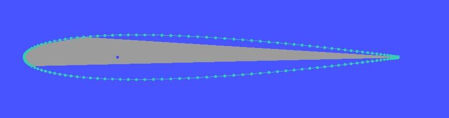 That didnt work, so I tried to segment my farfield into smaller sections and built the surfaces around the airfoil piece by piece as shown below: 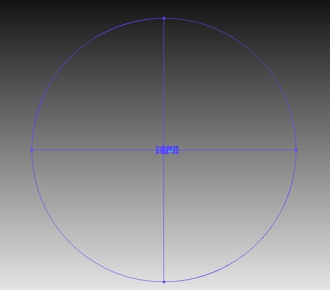 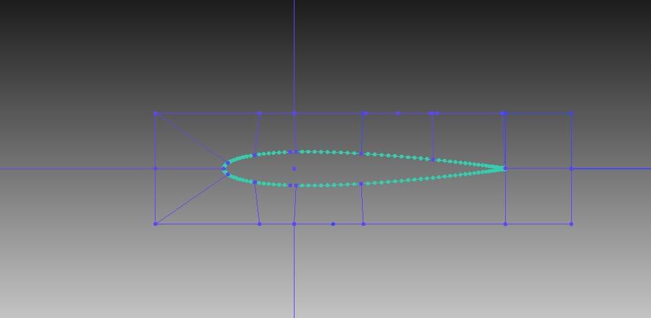 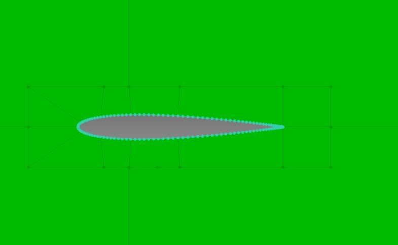 This now looks alot better. Then I proceeded to setup my mesh parameters, using parts mesh setup which is where I start to get confused. I would assume for the prism settings, you would probably need to designate where to grow your prism layers, which in this case will be the airfoil curve, but there is only a prism layer radio box on my farfield surface. But anyway I proceeded to setup my mesh as follows: 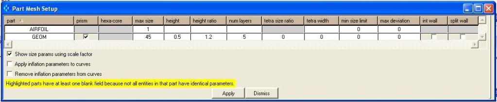 And this is what the mesher produced:- 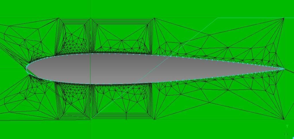 It looks like it is trying to build the boundary layers around the curves that I used to build the farfield surfaces which led me to think that the way I defined the surfaces is probably not correct, but I dont know how else I can do it. And I am also not sure if the geometry is supposed to be defined this way for 2dBlayer to work. So my question is 2 fold. 1. Geometry wise, has it been defined correctly for 2dblayer to work? If not Could you give me some pointers as to where I have gone wrong geometry wise and how it should be corrected so that 2dblayer can be used? 2. In terms of setting the mesh parameters up in parts mesh setup, am I setting up this wrongly? Ive got a feeling that its not correct, but that is probably due to 1., and I cant be sure about this. Sorry for the lengthy post but im really out of ideas right now. Thank you in advance and I hope to hear from you (or anyone out there) soon. Regards, Darren |
|
|
|
|
|
|
November 20, 2009, 19:50
|
|
#12 |
|
New Member
Alex
Join Date: Oct 2009
Posts: 6
Rep Power: 16 |
Kawamatt2,
I could not figured out how you use the "curve mesh setup" to add the structured boundary layer portion. Ok, you can prescribe these set up for the curve, but, afterwards what are your steps to create this sort of prism cap? You already had the tet mesh? regards, Alex |
|
|
|
|
|
|
December 3, 2009, 10:26
|
|
#13 |
|
New Member
Christian
Join Date: Dec 2009
Posts: 9
Rep Power: 16 |
hi!
i'm meshing a de laval-nozzle for 2D-simulations. my first step was to create an unstructured mesh in the nozzle an in the far field region. now i want to create a 2D-Blayer on the nozzle wall and afterwards extrude the whole mesh via rotation around the x-axis of the nozzle. i've already toggled the blayer 2d option in the advanced prism meshing parameters menu but i can not find out, how to toggle on the selection of curves for the prism meshing. can anyone tell me, what i have to type into the command line to switch on curve selection for prism meshing? extruding the mesh first and creating the prism afterwards doesn't work. i think that's due to the fact, that there's no surface mesh on the wall area. cheers, christian |
|
|
|
|
|
|
December 3, 2009, 20:03
|
|
#14 |
|
Member
Join Date: Sep 2009
Posts: 69
Rep Power: 16 |
Hi there,
I read a post somewhere where Simon said that there is a bug in the GUI for Prism mesh for Icem 12 for curves, and you need to use the TUI to do the settings. Ive given up on this method and ive just done a geometry extrude, do the prism mesh in 3d and extracted the surface mesh from that. Hope this helps. Regards, DarrenC |
|
|
|
|
|
|
December 4, 2009, 02:18
|
|
#15 |
|
New Member
Christian
Join Date: Dec 2009
Posts: 9
Rep Power: 16 |
Hi,
I found this thread where he posted, that you have to type something like "ic_geo_set_family...." in the Message window but for my case that didn't work. Perhaps because there are only curves an no surfaces in my part. I'm a student currently doing my Bachelor's-Thesis and I asked one of the PhD-students who is really an expert in CFD. He told me that i should use an O-grid for creating my structured Grid for the boundary layer. I will try this today and see what comes up next. Christian |
|
|
|
|
|
|
December 5, 2009, 15:03
|
|
#16 |
|
New Member
Join Date: Nov 2009
Posts: 14
Rep Power: 16 |
Thanks a lot Simon....I think there should be a tutorial which shows how to import, mesh and output for the different solvers for both 2d and 3d. It would have made my search lot easier.
|
|
|
|
|
|
|
December 10, 2009, 17:42
|
|
#17 |
|
Senior Member
Simon Pereira
Join Date: Mar 2009
Location: Ann Arbor, MI
Posts: 2,663
Blog Entries: 1
Rep Power: 47 |
Hello all,
1) 2D Prism is better than just offsetting (at least for CFD), but not as good as the front face of a 3D prism model. 2) 12.0 didn't allow you to turn on Prism for curves (GUI mistake). This is fixed for 12.1 which is now available. If you are using 12.0 and want to use BLAYER2D and need to turn on curve mesh parameters, you need to use commands like this... 7. ic_geo_set_family_params PRISMCURVE no_crv_inf prism 1 emax 5.0 emin 0.0 edev 0.0 8. ic_geo_set_family_params SURFACE2D no_crv_inf prism 1 emax 5.0 ehgt 0.0 hrat 0 nlay 0 erat 0 ewid 0 emin 0.0 edev 0.0 split_wall 0 Line 7) is for the curves. PRISMCURVE is just the part name. 5.0 is the max size. You can figure out the rest with the help of the programmers guide. If you use the replay script control or just cut and paste this in the message window, it will work. Line 8) is for the surface. When growing prism from curves with the BLayer2D option, you must also turn on Prism for the surface. You can do this thru the Part Mesh Setup (GUI) or you can do it with the replay or message window and a command similar to line 8). If typed correctly, this will work. 3) someone noted that using ICEM CFD Hexa is really the best way to mesh for one of these models... I totally agree. If you have ICEM CFD hexa, use it. 
|
|
|
|
|
|
|
December 1, 2010, 13:07
|
|
#18 |
|
Senior Member
Simon Pereira
Join Date: Mar 2009
Location: Ann Arbor, MI
Posts: 2,663
Blog Entries: 1
Rep Power: 47 |
Please help guide development at ANSYS by filling in these surveys
Public ANSYS ICEM CFD Users Survey This second one is more general (Gambit, TGrid and ANSYS Meshing users welcome)... CFD Online Users Survey |
|
|
|
|
|
|
March 3, 2014, 10:56
|
|
#19 |
|
New Member
LOTFI OULD ROUIS
Join Date: Jan 2014
Location: Canada
Posts: 23
Rep Power: 12 |
Hi Guys,
Could anyone tell me why does the inflation cuve setup doesn't work with the patch independent meshing? (Fig.1 and fig.2zoom). Suggestions would be more than appreciable  Thank you guys |
|
|
|
|
|
 |
| Thread Tools | Search this Thread |
| Display Modes | |
|
|
 Similar Threads
|
||||
| Thread | Thread Starter | Forum | Replies | Last Post |
| Gambit problems | Althea | FLUENT | 22 | January 4, 2017 03:19 |
| Boddy fitted Hexcore Mesh in ICEM Cfd | Mitch | CFX | 0 | December 29, 2008 06:07 |
| ICEM 10 mesh question | DAK565656 | CFX | 6 | May 8, 2007 12:16 |
| How to corse mesh in icem cfd? | Priety | CFX | 2 | October 2, 2006 03:57 |
| How to control Minximum mesh space? | hung | FLUENT | 7 | April 18, 2005 09:38 |
 1Likes


 Linear Mode


