|
|
|
[Sponsors] | ||||
 June 27, 2013, 08:42
|
|
#1 |
|
Member
ali
Join Date: Jun 2013
Posts: 44
Rep Power: 12  |
Hello I have a question about boundary condition in a dam bottom outlet. Boundary conditions are given as follows:
Inlet1 (Water): pressure=1204000 pa Inlet2 (Air): pressure=0 pa Outlet: Pressure=0 pa Problem is velocity value in air vent. Unfortunately, the speed obtained numerical model is much larger than the velocity in the physical model. Also, the amount of air pressure in the tunnel after the gate have to be negative, while the pressure is zero at this point. What is your suggestion to solve this problem? 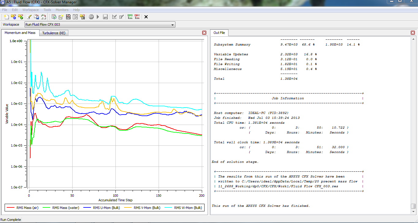
Last edited by ali92; June 27, 2013 at 11:44. Reason: The amount of air pressure in the tunnel after the gate ,on top of the flow,have to be zero not negative! |
|

|

|
|
|
June 27, 2013, 18:45
|
|
#2 |
|
Super Moderator
Glenn Horrocks
Join Date: Mar 2009
Location: Sydney, Australia
Posts: 17,700
Rep Power: 143 |
The air pressure in the air inlet and the outlet cannot be zero. There is going to be a small pressure difference across them which drives the air flow, but it will be tiny compared to the water inlet pressure.
But a more important point: Does this model need to be done as a multiphase model at all? At the massive pressure you have is the water confined to a known region at the bottom, so you could model this as a single phase water model (with the known free surface being modelled as a slip wall), and the air being modelled as a single phase with the free surface modelled as a wall with a tangential velocity equal to the water velocity? What are you trying to learn with this model anyway? |
|
|
|
|
|
|
June 28, 2013, 06:50
|
|
#3 |
|
Member
ali
Join Date: Jun 2013
Posts: 44
Rep Power: 12 |
A more accurate model is shown in Fig. As can be seen, there is a step in the model so that the air must be modeled in this situation.My goal is to compute the index Cavitation all over the tunnel.
The important thing is that flow before the gate is under pressure and after that is free surface. Air duct air velocity calculated by the software is invalid.(about 120 m/s)While the speed limit is 50 m/s. Where do you think the problem could be caused by? This can be due to the size of the mesh or mesh type or incorrect boundary condition? What is the correct boundary condition?(In Inlet1 pressure and flow rate is known.) What is the correct initial condition?(For the initial conditions, the volume fraction of water before gate is assumed one and after that is zero. Also it is assumed that water velocity is zero.) regards 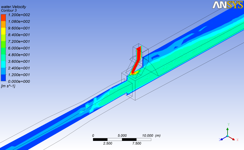
|
|
|
|
|
|
|
June 29, 2013, 07:26
|
|
#4 |
|
Super Moderator
Glenn Horrocks
Join Date: Mar 2009
Location: Sydney, Australia
Posts: 17,700
Rep Power: 143 |
This is an FAQ: http://www.cfd-online.com/Wiki/Ansys..._inaccurate.3F
I can see from the blockyness of your contours that your mesh is far too coarse. That is definitely one error, there may be others. |
|
|
|
|
|
|
June 29, 2013, 16:24
|
|
#5 |
|
Member
ali
Join Date: Jun 2013
Posts: 44
Rep Power: 12 |
Thanks a lot for your kind help.
|
|
|
|
|
|
|
July 3, 2013, 12:38
|
|
#6 |
|
Member
ali
Join Date: Jun 2013
Posts: 44
Rep Power: 12 |
I have read the above file.
In a steady state, to achieve a reasonable answer, how many iterations are needed? The answer does not converge to a residual set. What is the solution for this problem? 
|
|
|
|
|
|
|
July 3, 2013, 19:06
|
|
#7 |
|
Super Moderator
Glenn Horrocks
Join Date: Mar 2009
Location: Sydney, Australia
Posts: 17,700
Rep Power: 143 |
This is an FAQ as well: http://www.cfd-online.com/Wiki/Ansys...gence_criteria
|
|
|
|
|
|
|
July 4, 2013, 05:55
|
|
#8 |
|
Member
ali
Join Date: Jun 2013
Posts: 44
Rep Power: 12 |
How do you choose correct physical time scale?
FAQ said: Use a larger physical time step. A time step approximately equal to the average residence time in the simulation domain is a good guide for most simulations. If it is a recirculating system without an inlet or outlet then use the turn over time of the largest flow feature. You can get the residence time in CFX-Post by placing a streamline and looking at the "Time" variable on it. The maximum value of time is the residence time. Large and different quantities can be obtained with this method. Because I do not know what start from should be chosen in streamline window? For example: 1.98e14 !!!!! Which boundary should be chosen as start from? inlet1,inlet2,outlet,gate section or else? Regards |
|
|
|
|
|
|
July 4, 2013, 07:24
|
|
#9 |
|
Super Moderator
Glenn Horrocks
Join Date: Mar 2009
Location: Sydney, Australia
Posts: 17,700
Rep Power: 143 |
As I said in the other post, start with auto time scale and use edit run in progress to increase it. Don't be timid, use time scale factors of 10, 100 or 1000. If it is too big it will start going numerically unstable. If it is too small it will take ages to converge or not converge at all.
|
|
|
|
|
|
|
July 4, 2013, 09:18
|
|
#10 |
|
Member
ali
Join Date: Jun 2013
Posts: 44
Rep Power: 12 |
I am really appreciate your help!

|
|
|
|
|
|
|
July 6, 2013, 03:01
|
|
#11 |
|
Member
ali
Join Date: Jun 2013
Posts: 44
Rep Power: 12 |
I used auto timescale with different timescale Factor.If it is greater than 12, the program gives error 255. With this timescale factor:
RMS U,V,W>1e-4 RMS air,water<1e-4 Velocity: is converged (50m/s) Pressure is converged. Imbalance: 0.04% Is this an acceptable answer? Why do not converge solution with increasing time step? Is it: -The coarse mesh? -Local effect? Mesh used is as follows: Mesh type: tetrahedral Mesh sizing: -Min size: .03 -Max face size: 1.5 -Max size: 2 Body sizing: .4 m Face sizing: .2 m Elements: 1602597 I used Aggressive, but the program gave Error. I used High resolution in Turbulence Numeric, but the results did not change. I used Blend factor .75 in Advection scheme , but the results did not change. Rate is larger than .95. Is it a problem? It is said MAX Residuals should be smaller than 1e-3 . Is it true? It is said MAX should be one order larger than RMS? Is there this in my results? I read manuals but: 
Last edited by ali92; July 6, 2013 at 05:55. |
|
|
|
|
|
|
July 6, 2013, 03:10
|
|
#12 |
|
Member
ali
Join Date: Jun 2013
Posts: 44
Rep Power: 12 |
These pictures are added:
|
|
|
|
|
|
|
July 6, 2013, 06:25
|
|
#13 |
|
Super Moderator
Glenn Horrocks
Join Date: Mar 2009
Location: Sydney, Australia
Posts: 17,700
Rep Power: 143 |
This question in an FAQ: http://www.cfd-online.com/Wiki/Ansys...gence_criteria
Mesh quality will help, and I bet this simulation is not steady state anyway but requires transient for convergence. Just a guess, but I have seen this type of behaviour many times before
|
|
|
|
|
|
|
July 6, 2013, 06:42
|
|
#14 |
|
Member
ali
Join Date: Jun 2013
Posts: 44
Rep Power: 12 |
thanks.
Yes. I know my simulation is transient. At first I do so. But for compression with physical model I need to simulate steady. |
|
|
|
|
|
|
July 6, 2013, 06:53
|
|
#15 |
|
Member
ali
Join Date: Jun 2013
Posts: 44
Rep Power: 12 |
thanks.
Yes. I know my simulation is transient. At first I do so. But for compression with physical model I need to simulate steady. |
|
|
|
|
|
|
July 6, 2013, 07:12
|
|
#16 |
|
Super Moderator
Glenn Horrocks
Join Date: Mar 2009
Location: Sydney, Australia
Posts: 17,700
Rep Power: 143 |
What do you mean by "But for compression with physical model I need to simulate steady."
|
|
|
|
|
|
|
July 6, 2013, 07:19
|
|
#17 |
|
Member
ali
Join Date: Jun 2013
Posts: 44
Rep Power: 12 |
Excuse me.
For Comparison with physical model I need to simulate steady. I do not have result of physical model in different time. |
|
|
|
|
|
|
July 6, 2013, 07:41
|
|
#18 |
|
Super Moderator
Glenn Horrocks
Join Date: Mar 2009
Location: Sydney, Australia
Posts: 17,700
Rep Power: 143 |
If the simulation is really steady then a transient model will converge to the steady solution. So, as the FAQ says, try running transient and converge to steady state that way.
|
|
|
|
|
|
|
July 6, 2013, 07:42
|
|
#19 |
|
Member
ali
Join Date: Jun 2013
Posts: 44
Rep Power: 12 |
Is it correct that I simulate a steady simulation instead of transient?
How were pictures? |
|
|
|
|
|
|
July 6, 2013, 07:46
|
|
#20 |
|
Super Moderator
Glenn Horrocks
Join Date: Mar 2009
Location: Sydney, Australia
Posts: 17,700
Rep Power: 143 |
The FAQ I linked to explains it in detail. If you are having problems converging using a steady state model try a transient model. It often converges better and achieves your convergence tolerance. But you will need to run it for long enough to get the steady state result - if there is one.
|
|
|
|
|
|
 |
|
|
 Similar Threads
|
||||
| Thread | Thread Starter | Forum | Replies | Last Post |
| outlet problem | FabOr | OpenFOAM | 0 | May 28, 2010 08:19 |
| ATTENTION! Reliability problems in CFX 5.7 | Joseph | CFX | 14 | April 20, 2010 15:45 |
| problem of without inlet and outlet | dwarika nath rath | Phoenics | 2 | March 11, 2004 17:10 |
| TASCflow simulation result problem? | Mason | CFX | 0 | February 22, 2004 07:54 |
| what the result is negatif pressure at inlet | chong chee nan | FLUENT | 0 | December 29, 2001 05:13 |
 1Likes
 Linear Mode


