|
|
|
[Sponsors] | ||||
 August 1, 2007, 17:44
|
|
#1 |
|
Guest
Posts: n/a
|
Hello. Does any body can explain the parameter PITCH CHANGE, when you make a connection of the Rotor-Stator? i read the Ansys manua,l, but then dont explain to clear. When I haveto use automatic? when none? when specified pitch angles? (which angles), when values? wich value?
Thanks a lot. Santiago |
|

|
||
|
August 2, 2007, 04:57
|
|
#2 |
|
Guest
Posts: n/a
|
Hi Santiago,
I use this option while setting up a simulation consisting of a single rotor and single stator blade. Under most circumstances, CFX is able to identify the pitch change correctly by using Automatic option. But in some cases with multiple connections i have noticed that CFX fails to do so in such cases it is best to specify the pitch angles individually on either sides. When there is pitch change, a transformation is also performed between components to account for the fact that they may not be rotationally aligned. This does not affect the relative position of the components. In Figure 6 the components are not aligned; flow passes through the overlapping area as expected, but the flow that reaches the interface at 1 is transformed such that it emerges at 2 having crossed the interface. |
|
|
|
||
|
August 2, 2007, 09:14
|
|
#3 |
|
Guest
Posts: n/a
|
The Pitch Change is the change in the sector size on either side of the interface. Since you would never create a rotor and stator with the same number of blades (if you did you would run into major vibration issues) and rarely an evenly divisible numer of components, the solver must be able to account for the change in pitch as it moves from one periodic domain to another. For instance, the mass flow rate will change across the interface by the same ratio as the change in pitch (to maintain the same total mass flow rate for the 360 degree machine)
The solver can calculate the pitch change automatically based on the area ratio of the sides of the interface. This works if the hub and shroud are lined up on either side of the interface and the meshes are of similar resolution. Since the curved edges are represented by discrete lines in the mesh, a small error in the calculation of area will exist. If the mesh resolution is very different, the difference in area on either side will still be small but may be enough to throw off the solution a bit. The automatically calculated pitch change is reported in the out file just before the iterations begin. You should check this to see if it is correct for you configuration. A non-overlap area in the circumferential direction is expected and the solver transforms the flowfield across the interface to account for this. However, if the hub and shroud don't line up, the non-overlap area in the axial/radial direction will result in an incorrect calculation of the pitch change. In this case (or if the mesh is quite different as above) you should specify the pitch change explicitely. If you are modeling a full 360 degree machine or you have a case where the mesh lines up at all the edges and there is no change in pitch (for instance, if you were connecting an impeller with a vaneless diffuser of the same pitch), you can specify the pitch change to none. This saves some work for the solver and can prevent issues that would otherwise arise for a full 360 degree machine. Regards, Robin |
|
|
|
||
|
August 2, 2007, 10:26
|
|
#4 |
|
Guest
Posts: n/a
|
Thanks Robin for your answer. You really cleared some things.
Im having this problem. 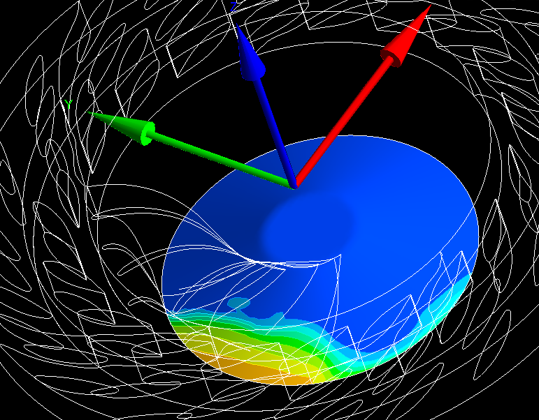 Im modelling 4 passages in Stator and 3 passages in rotor. Im using Stage connection between Stator -Rotor and Between rotor-draft tube. As you can see in the pic of the simulation , it seems like the solver its only passing information from stator-rotor, (periodic), but no from rotor-draft. It only passes the information of the 3 passages modelled, so thats why the pic (velocity plot) show only some influence in the orange-yellow-green part, and not to all the 360 degrees of the machine. Do you know the problem? Thanks a lot. Santigao. |
|
|
|
||
|
August 2, 2007, 10:58
|
|
#5 |
|
Guest
Posts: n/a
|
I can't make out your geometry in this view. Can you color each component differently and post a few more views?
Before you do, have you tried contacting technical support? They're there to help you with this kind of thing. Regards, Robin |
|
|
|
||
|
September 21, 2016, 04:57
|
|
#6 |
|
Senior Member
Brett
Join Date: May 2013
Posts: 212
Rep Power: 13  |
What does 'pitch' itself refer to? is that just the angular orientation of a flow element?
|
|

|
|
|
 |
|
|
 2Likes
 Linear Mode


