|
|
|
[Sponsors] | ||||
why lift coefficients don't converge at high angle of attacks? |
 |
|
|
LinkBack | Thread Tools | Search this Thread | Display Modes |
 January 11, 2012, 12:46
|
|
#1 |
|
Member
Ming Cai
Join Date: Mar 2011
Posts: 50
Rep Power: 15  |
Dear Friends
I'm running simulation on a NACA 64 210 airfoil with k-omega sst model with Re = 2.6 E6 . The chord length is 1m. Angle of Attack ranges from 0 to 20. I'm changing the inlet velocity for different angles. Mesh is shown below 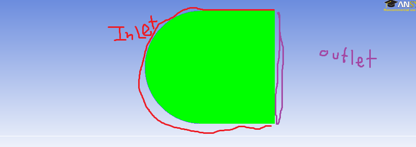 everything is fine before angle of attack getting to 12 degree, both lift coefficient and drag coefficients oscillates periodicly after 12 degree  I don't know if this is the correct solution. However, before this angle the results are reasonable  Is it because of the mesh? Does it mean changing inlet velocity is not correct for higher degree angles of attack? Thanks for your help. |
|

|

|
|
|
January 11, 2012, 12:52
|
|
#2 |
|
Senior Member
cfdnewbie
Join Date: Mar 2010
Posts: 557
Rep Power: 20 |
Hi,
I'm no expert on steady calculations, but I would guess that with increasing AOA, your problem becomes ever more "transient", since (in reality) you would see serious vortices rolling up from the nose and shedding with some characteristic frequency.... So I guess that a steady approximation of this unsteady problem has reached its limits, and the RANS has problems converging to a steady state. Hope this helps, maybe the RANS guys here could confirm / refute? Cheers |
|
|
|
|
|
|
January 11, 2012, 14:04
|
|
#3 | |
|
Member
Ming Cai
Join Date: Mar 2011
Posts: 50
Rep Power: 15 |
Quote:
I have no experiences in wind tunnel tests at all. Hope some experts could help me out |
||
|
|
|
||
|
January 11, 2012, 16:12
|
|
#4 |
|
Senior Member
Martin Hegedus
Join Date: Feb 2011
Posts: 500
Rep Power: 19 |
Are you using local or global time stepping? Is your grid structured or unstructured? If you are using local time stepping with a structured grid and the grid cells become small compared to others in the near vicinity (such as one finds at the trailing edge), you'll get a spatial variation of time step which could also cause the flow to go unstable. The small structured grid cells create a blockage.
|
|
|
|
|
|
|
January 11, 2012, 16:44
|
|
#5 |
|
Senior Member
cfdnewbie
Join Date: Mar 2010
Posts: 557
Rep Power: 20 |
Adding to the points mentioned by Martin: Explicit or implicit time stepping? if you are doing RANS, I'd guess implicit....if so, check your CFL, maybe your steady solver actually starts to pick up unsteadiness....
|
|
|
|
|
|
|
January 11, 2012, 17:14
|
|
#6 |
|
Member
Ming Cai
Join Date: Mar 2011
Posts: 50
Rep Power: 15 |
Thanks for all your replies.
  I'm using unstructured mesh, and transient formulation is implicit. I had changed to run for steady state solution, I got converged solution 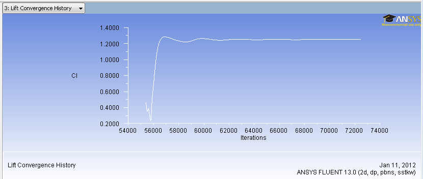 I'm not sure why transient solution would oscillate.... |
|
|
|
|
|
|
January 11, 2012, 18:36
|
|
#7 | |
|
Senior Member
cfdnewbie
Join Date: Mar 2010
Posts: 557
Rep Power: 20 |
Quote:
|
||
|
|
|
||
|
January 11, 2012, 18:41
|
|
#8 | |
|
Member
Ming Cai
Join Date: Mar 2011
Posts: 50
Rep Power: 15 |
Quote:
I should read more about airfoil stalling... I don't really understand how experimental people measure Lift and Drag at this angle.... I found some experimental results for comparison and they only show a single value for this. Can you recommend me some book talks about lift and drag measurement at stalling angles? |
||
|
|
|
||
|
January 12, 2012, 14:17
|
|
#9 |
|
Senior Member
Vieri Abolaffio
Join Date: Jul 2010
Location: Always on the move.
Posts: 308
Rep Power: 16 |
High AoA foils Cl is avaraged in the wind tunnel over a certain time. this is to have a sinlge meaniningful result of a phenomenon wich is unsteady.
More specifically, a stalled foil will be charachterized by grat separation, setachment and consequently vortex generation in the wake. While a steady RANSE will converge to a certain value, it will probaly be wrong. Not only a numerical avaraging will loose and/or smear lot of high intensity phenomenon, but usually ranse turbulence models will not be able to predict accurately the detachemnt and the other physics that take place. if you need some meaningful results, I would recomand to switch to LES symulations. https://www.youtube.com/watch?v=J-xxCkebdZs here you can see exactely what happens in the stall and pre stall phase. |
|
|
|
|
|
|
January 12, 2012, 15:12
|
|
#10 | |
|
Member
Ming Cai
Join Date: Mar 2011
Posts: 50
Rep Power: 15 |
Quote:
|
||
|
|
|
||
|
January 12, 2012, 15:14
|
|
#11 |
|
Senior Member
Martin Hegedus
Join Date: Feb 2011
Posts: 500
Rep Power: 19 |
In the beginning Ming mentions that his Re is 2.6e6. His RANS solutions, even up to 20 degrees, are probably OK, everything considered. LES will be expensive. And, I wouldn't necessarily trust the WT results passed stall either. The side walls can affect the results.
|
|
|
|
|
|
|
January 13, 2012, 06:17
|
|
#12 | |
|
Senior Member
Vieri Abolaffio
Join Date: Jul 2010
Location: Always on the move.
Posts: 308
Rep Power: 16 |
Quote:
While i'm just starting to "play" with LES, i agree that it is expansive, even if i've seen quite good results even using wall functions or DES. It all depends on the pourpuse of the analysis, maybe some tradeoffs are necessary accomplish the goal. |
||
|
|
|
||
|
January 13, 2012, 12:05
|
|
#13 | |
|
Senior Member
Martin Hegedus
Join Date: Feb 2011
Posts: 500
Rep Power: 19 |
Quote:
What follows is my impression only. Overall, when done right for an airfoil, I feel LES is better than RANS, ignoring the time penalty. In general, i.e. arm waving, when Re gets below 1e6-2e6 I do start feeling uncomfortable with RANS. Above this, LES and RANS start approaching one another for tripped results. From what I understand, neither do well for transition (i.e. drag buckets) unless the turbulence models get tweaked. But there is a lot of research in this area and I do not claim to be up to date. Then there is the wind tunnel results. One needs to be careful that the walls above and below the airfoil are far away. Unfortunately I don't have a rule of thumb. But I would say at a minimum 10 times the chord. In general you will not find that. I've seen CFD results miss the cl lift curve slightly and claim it is the turbulence model. The turbulence model gets switched, usually SA to SST, better agreement is obtained, and success is claimed. But if one models the walls, they may find that the SA is better. Then there is separation. Usually the airfoil is mounted on a turn table or splitter plate. This, along with any upstream BL which is influencing the results, is enough to cause the the airfoil sides to stall first. This tends to delay stall at the center section where the pressure taps and rake are. In regards to RANS, it is nice to seen when people model the WT. Or at least just a box around the airfoil. For values before stall it is OK to give the walls a slip condition. Then one does not need to worry about boundary layers. Then do like the experiment. Calculate lift by integrating the pressure and calculate drag by using a rake. If you calculate drag by integrating the surface values, you'll find that the answer may be off if the WT walls are affecting the results. The reason is that the rakes do not go far enough to capture wall effects. In regards to the region of stall, I don't have best practices in regards to modeling the WT wall boundary layer. But something is nice. Maybe best and worst cases. |
||
|
|
|
||
|
January 13, 2012, 15:38
|
|
#14 |
|
Member
Ming Cai
Join Date: Mar 2011
Posts: 50
Rep Power: 15 |
Thanks for your guys discussion~ I learnt a lot from this ~
|
|
|
|
|
|
|
|
|
 Similar Threads
|
||||
| Thread | Thread Starter | Forum | Replies | Last Post |
| [Netgen] Import netgen mesh to OpenFOAM | hsieh | OpenFOAM Meshing & Mesh Conversion | 32 | September 13, 2011 05:50 |
| convegence problem with high angle of attack | littlelz | CFX | 2 | October 28, 2009 06:07 |
| Lift and Drag Coefficients Reliability | Luis | FLUENT | 2 | December 27, 2005 14:45 |
| Multicomponent fluid | Andrea | CFX | 2 | October 11, 2004 05:12 |
| High lift analysis using overset | kei-tee | Main CFD Forum | 0 | April 10, 2003 09:53 |
 5Likes


 Linear Mode


