|
|
|
[Sponsors] | ||||
chtMultiregionFoam--unequal temperature at coupled patches |
 |
|
|
LinkBack | Thread Tools | Search this Thread | Display Modes |
 September 6, 2012, 11:05
|
|
#1 |
|
Member
zakir
Join Date: Nov 2011
Posts: 44
Rep Power: 14  |
Hello everyone
I use chtMultiregionFoam to simulate a heat transfer problem.I just modified the energy equation to steady state.But I found that the temperature fields at a coupled boundary patch do not match the temperature field of the adjacent coupled boundary patch of another mesh region.I plot my result in tecplot360 and it really shows that there are two values on the interface of solid and fluid. I have attached my model (cross profile,flow is perpendicular with it) ,2d temperature contours ,3d temperature contours( you can find that it is discontinuous)and temperature curve along x axis(you can see the temperature jump at the interface). I hope you can give me some advice or solution to solve this problem.Thank you very much! regards! zakir |
|

|

|
|
|
September 9, 2012, 13:11
|
|
#2 |
|
Retired Super Moderator
Bruno Santos
Join Date: Mar 2009
Location: Lisbon, Portugal
Posts: 10,975
Blog Entries: 45
Rep Power: 128  |
Hi Zakir,
I've updated my response on the other thread you asked me about the other day: http://www.cfd-online.com/Forums/ope...d-patches.html - check post #2 It's not a direct answer, but it should get you to the solution! Good luck! Bruno
__________________
|
|
|
|
|
|
|
September 10, 2012, 21:06
|
|
#3 |
|
Member
zakir
Join Date: Nov 2011
Posts: 44
Rep Power: 14 |
Hi everyone
I have attached the residuals here.I think all residuals have been below 1e-4 So the solution have been convergent.But why can't I get a good result still? regards! zakir |
|
|
|
|
|
|
September 11, 2012, 10:25
|
|
#4 |
|
Member
zakir
Join Date: Nov 2011
Posts: 44
Rep Power: 14 |
Dear all
I am almost crazy for getting a correct temperature curve.These days I also have tried the conjugateHeatFoam of version 1.6-ext and run the tutorial called conjugateCavity.Code or case are original.After the solution became convergent,I used paraview and tecplot for post processing.I have attached the pictures here.Maybe I am wrong in post processing operation.So I will give the detail steps,I hope you can give me some advice. 1.I chose the last time result and Meshregion (internalMesh and solid/internalMesh ),then applied. 2.I used the 'slice' funciton to create a plane parallel to the xy plane and through the center of thickness. 3.I used the 'plot over line' filter,and chose a line parallel to the x axis. And I got the temperature xy plot. The last one is I plot with tecplot360. I hope you can take some minutes to it and tell me where is the mistake I have made.Thank you very much! regards! zakir |
|
|
|
|
|
|
September 11, 2012, 17:12
|
|
#5 |
|
Retired Super Moderator
Bruno Santos
Join Date: Mar 2009
Location: Lisbon, Portugal
Posts: 10,975
Blog Entries: 45
Rep Power: 128 |
Hi Zakir,
Do you know if you're plotting the values from the center of the cells, or from the faces/point interpolations? Nonetheless, this is one of those situations where you better first validate if your steps are correct or not. I suggest that you do the following exercise, to validate/confirm what you're doing and how you're analyzing the results:
Best regards, Bruno
__________________
|
|
|
|
|
|
|
September 14, 2012, 10:52
|
|
#6 |
|
Member
jack
Join Date: Jul 2011
Posts: 52
Rep Power: 14 |
I have met the same problem with you!If you have solved the problem,just let me know!Thank you
regards! lg88 |
|
|
|
|
|
|
September 14, 2012, 11:09
|
|
#7 |
|
Member
zakir
Join Date: Nov 2011
Posts: 44
Rep Power: 14 |
Hello Bruno
I have tried what you told me."a simple case with two water and/or air volumes separated by a flat solid plate, with both fluids flowing along the wall."Although I didn't compared the result with analytical solution,it is wrong.It was so obvious. The residuals have been convergent,But the temperature still have the same problem in the interface.And the velocity at the interface is not zero.It is strange.I have attached the result here.The first one is the 3D velocity contour.The second is the residuals.The third is the 2d velocity slice.The last one is the temperature field changes along the white line in the third picture.Maybe I have made some mistakes in the setting of the case.Or I have done some wrong operation in the post-processing.But I have checked the case again and again.I hope you can give me some idea.Thank you very much. regards! zakir |
|
|
|
|
|
|
September 15, 2012, 07:52
|
|
#8 |
|
Retired Super Moderator
Bruno Santos
Join Date: Mar 2009
Location: Lisbon, Portugal
Posts: 10,975
Blog Entries: 45
Rep Power: 128 |
Hi Zakir,
Now that you have a simple case prepared, it'll be easier for us to work together to figure out if this is a setup problem or a bug in OpenFOAM. Please package this simple case you have, preferably in a similar way as the tutorials that come with OpenFOAM, namely in a state right before the mesh is generated. In case you don't know, you can package the case by running the following command in the parent folder: Code:
tar -czf simple_case.tar.gz simple_case Best regards, Bruno
__________________
|
|
|
|
|
|
|
September 21, 2012, 10:53
|
|
#9 |
|
Member
zakir
Join Date: Nov 2011
Posts: 44
Rep Power: 14 |
Hi Bruno
I am sorry for late updating my poster because I have been outside for days. I have created a different case which contains heat transfer between solids only.And I did the post-processing as what I said before.The T xy plot is just along the short white line in the second picture. The version I used is OF-1.6-ext regards! zakir |
|
|
|
|
|
|
September 23, 2012, 11:34
|
|
#10 |
|
Retired Super Moderator
Bruno Santos
Join Date: Mar 2009
Location: Lisbon, Portugal
Posts: 10,975
Blog Entries: 45
Rep Power: 128 |
Hi Zakir,
I went to bed last night and woke up this morning thinking about doing this example. Attached you will find:
The mesh of this example case "planeWall2D" is based on the cavity case, but with 1m x 1m. It's divided into 3 regions:
Code:
./Allrun Code:
./Allclean Nonetheless, I do not get strange results as the ones you're getting Zakir. This is why I say this a very good example for you to diagnose what is going on! Additional exercises that are left to anyone who's reading this:
Bruno PS: I've added this to the openfoamwiki.net: http://openfoamwiki.net/index.php/Ge..._-_planeWall2D To all forum readers, feel free to improve that page!
__________________
Last edited by wyldckat; September 23, 2012 at 13:12. Reason: forgot to mention the OpenFOAM version; added "PS:" as well |
|
|
|
|
|
|
September 24, 2012, 03:53
|
|
#11 |
|
Super Moderator

Tobias Holzmann
Join Date: Oct 2010
Location: Tussenhausen
Posts: 2,708
Blog Entries: 6
Rep Power: 51   |
Hi all,
@zakir: You always get temperature differences at the interface and that depends on the flow and viscose layer -> 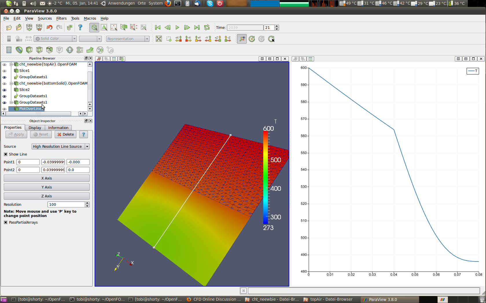 Therefor its very important to refine your FLUID region to the boundary to get right resolution. I have no time to read all the lines here but your Heat-Transfer seems "relative correct" ... Here is a case I made for a guy this year: http://ww3.cad.de/foren/ubb/Forum527...5.shtml#000010 Maybe bruno solved your problem  ---------------- Kind Regards T. Holzmann |
|
|
|
|
|
|
December 19, 2013, 10:40
|
|
#12 |
|
Member
Kumudu
Join Date: Oct 2013
Posts: 63
Rep Power: 12 |
Hi,
I want to simulate temperature of a ground heat exchanger. I have attached the schematic of ground heat exchanger. This ground heat exchanger is consisted with a borehole ( cylindrical hole dig in the soil). Inside the borehole, there is a U-tube (water is circulating). The borehole is filled with a soil like material called grout. I just want to know how the temperature of soil, grout and fluid is varied with time and depth. Fluid (water) is circulated in the U-pipe with constant flow rate. Can you tell me how to define the boundary condition for fluid(water) region? I defined three cell zones(waterInPipe1,waterInPipe2,waterInPipeConnect ) for fluid as it is a U-loop. waterInPipe1: At the top ,velocity InletOutlet inletValue: (0,0,-10) (-z direction) For all boundaries, except interface between waterInPipeConnect and waterInPipe1): fixedValue, uniform (0,0,0) At the interface (waterInPipeConnect and waterInPipe1):velocity boundary conditions outletInlet outletValue (4,0,0) (x-diraction) Similar case for waterInPipe2 Question: 1. will this velocity boundary condition works?(because this should have a continuous flow) 2. how to define temperature for fluid-fluid interface 3. How to define constant mass flow rates in the whole fluid region(waterInPipe1, waterInPipe2 and waterInPipeConnect)? 4. How to define pressure at each fluid region (I don't want to simulate pressure and as the mass flow rate is constant, I think pressure is also constant)? 5. how to define k, P,P_rgh,Ychar,Ypmma for each of these region? I mean what would be the boundary and initial conditions for these values in fluid regions( I just know the mass flow rate value only, I don't know about the pressure values) 5.what are these Ychar,Ypmma stand for why we have P and P_rgh ( I don't know about this) Please give me some advice to do this. The flow is incompresible and has a constant mass flow rate. To fluid to pipe, convection heat transfer is exist. I want to find convective heat transfer coefficient as well. Thanks in advance Kumudu |
|
|
|
|
|
|
December 19, 2013, 16:34
|
|
#13 |
|
Super Moderator
Tobias Holzmann
Join Date: Oct 2010
Location: Tussenhausen
Posts: 2,708
Blog Entries: 6
Rep Power: 51 |
Hi Kumudu,
a lot of question you are asking are describt in the tutorials. Please have a look at one tutorial then you will see how to set your BC. You will find to set: - U - T - p - p_rgh - k - epsilon Additionally: p = total pressure p_rgh = p - rho *gh (total pressure - hydrodynamic pressure) You inlet BC for U should be a fixedValue. Not inletOutlet. To define your BC please refer to the tutorials. You set every condition and initial solution in the folder 0/ Regards Tobi |
|
|
|
|
|
|
December 19, 2013, 17:22
|
|
#14 |
|
Member
Kumudu
Join Date: Oct 2013
Posts: 63
Rep Power: 12 |
Hi Tobi,
Thanks for the reply. Can you send me a link for chtMultiRegionFoam tutorial. I have gone through planeWall 2D tutorial. But, I didn't exactly find answer to my questions. So, at the fluid -fluid interface, how should I set the boundary conditions for velocity and temperature. I have seen only solid-fluid interface interaction example. But, can you explain, boundary conditions for pressure at fluid-fluid interface as well. At the inlet, of the first and second pipe, I have to give the zeroGradient for pressure. I think this would be the same for fluid-fluid interface. Am I correct? |
|
|
|
|
|
|
December 20, 2013, 06:31
|
|
#15 |
|
Super Moderator
Tobias Holzmann
Join Date: Oct 2010
Location: Tussenhausen
Posts: 2,708
Blog Entries: 6
Rep Power: 51 |
Hi,
I had a look at your document and did not see any fluid-fluid Interface ? At least a fluid fluid Interface is not possible in my physical world  - only if you have two immiscible fluids like air - water. If you have water water you always Need a solid between, aren´t you - only if you have two immiscible fluids like air - water. If you have water water you always Need a solid between, aren´t you  Hmmm if you are asking for tutorials it seems that you are a beginner with openfoam. Did you ever read the user-guide? Code:
mkdir -p $FOAM_RUN cp -r $FOAUM_TUTORIALS $FOAM_RUN cd $FOAM_RUN cd tutorials/heatTransfer/chtMultiRegionSimpleFoam/ Regards Tobi |
|
|
|
|
|
|
December 20, 2013, 09:00
|
|
#16 | |
|
Member
Kumudu
Join Date: Oct 2013
Posts: 63
Rep Power: 12 |
Quote:
Hi Tobi, Thanks for the reply. Yes.I am new to OpenFoam and I thought you are talking about some tutorials available in Internet. I went through the tutorial in the OpenFoam , run directory. Actually, I divided my fluid domain into three regions waterInPipe1,waterInPipe2, waterInPipeConnect since I wanted to define the fluid region using only topoSetDict without defining different blocks in the blockMesh. Yes, I know that I can define this water in the pipe as a one fluid region.Then, I will have one inlet and outlet and others are walls. As I wanted to change the diameter and length of the U-pipe and simulate again and again, I just defined it as three fluid regions. So, is there any easy method to define this U-pipe as a one fluid region and change the diameter and length whenever I want to change? Thanks again |
||
|
|
|
||
|
December 29, 2013, 16:35
|
|
#17 |
|
Retired Super Moderator
Bruno Santos
Join Date: Mar 2009
Location: Lisbon, Portugal
Posts: 10,975
Blog Entries: 45
Rep Power: 128 |
For future readers: the line of questions and answers for Kumudu's problem is continued on this thread: http://www.cfd-online.com/Forums/ope...egionfoam.html
|
|
|
|
|
|
|
| Tags |
| unequal temperature |
|
|
 Similar Threads
|
||||
| Thread | Thread Starter | Forum | Replies | Last Post |
| [OpenFOAM] plot temperature vs time in paraview - chtMultiRegionFoam | phsieh2005 | ParaView | 2 | March 16, 2014 06:50 |
| Inlet won't apply UDF and has temperature at 0K! | tccruise | Fluent UDF and Scheme Programming | 2 | September 14, 2012 06:08 |
| chtMultiRegionFoam - exchange data between flow field and temperature | phsieh2005 | OpenFOAM Running, Solving & CFD | 0 | February 7, 2012 09:16 |
| High temperature methane+air | Peter | FLUENT | 5 | January 26, 2009 18:04 |
| Help! Coupled Vs Implicit - Total temperature | sile | FLUENT | 3 | March 10, 2003 15:58 |
 1Likes

 Linear Mode


