|
|
|
[Sponsors] | ||||
 February 7, 2012, 23:34
|
|
#1 |
|
New Member
Matt
Join Date: Feb 2012
Location: Mankato, MN - St. Louis, MO
Posts: 12
Rep Power: 14  |
I will preface by saying I'm a newbie, but some of my peers can't quite figure it out either. I will explain as best I can.
I built an intake manifold and tube assembly in Pro/E, converted it to a STEP file and imported into Star. The manifold is hollow, it has 1 inlet, and the 3 outlets for each cylinder. I used the holes for the outlets and inlet in the surface repair tool and named them accordingly. I did notice when using the surface repair, when converting to STEP there were some holes created in the manifold. Could that be the cause of this problem: when performing the surface mesher, it creates the mesh pictured below, when trying to use the re-mesher, it gives error saying volume not closed. So, I tried operations>extract volume and it says "could not find appropriate topological region" So my questions are: Should this work if I fix the holes? Should I try an IGS file instead? Should I use the cut-out/merge tool to cutout the interior volume of the intake assembly AND THEN import it into Star?  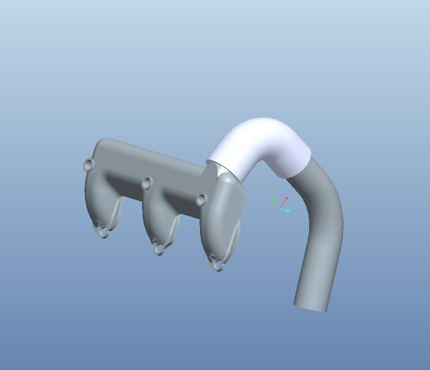 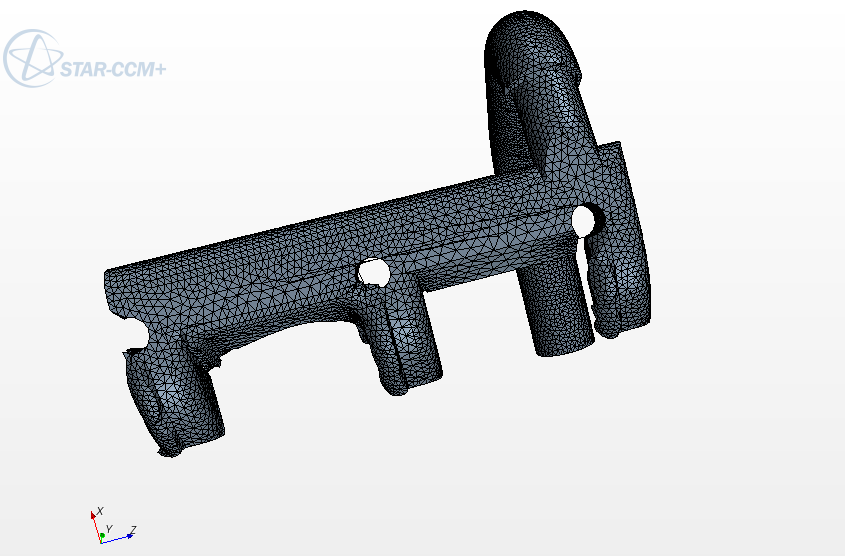
|
|

|

|
|
|
February 8, 2012, 03:02
|
|
#2 |
|
Member
Join Date: Feb 2011
Location: DE-PB
Posts: 56
Rep Power: 15 |
Start with importing your geometry at the 3D-CAD-modeler. If more than one body is imported, use the boolean Unite operation to make one body from all.
Close the CAD-modeler and assign your bodies to parts. Launch the surface repair tool and close all holes (Inlet and 3 Outlets). By the way you can make an diagnostic at the surface repair to check if your geometry has got any non-manifold or free edges issues. After the holes has been closed you can use the Split by surface topologie operation. This will split the part into two new parts, the manifold and the internal volume which you will need for your exhaust gas region. Assign the parts to regions and mesh them. By the way your mesh picture seems that feature curves are missing, so compute part curves before you assign your parts to regions. I hope this will help. |
|
|
|
|
|
|
February 9, 2012, 15:21
|
|
#3 |
|
New Member
Matt
Join Date: Feb 2012
Location: Mankato, MN - St. Louis, MO
Posts: 12
Rep Power: 14 |
Hi,
Thank you very much for your reply. However, it didn't work. I followed your instructions, I imported the model into the 3D-CAD_MODELER. It was an assembly that was imported, so it was one full body. I tried to Unite anyway, as it was still listed as 3 separate entities under "Parts" But it wouldn't let me; brought up an error: "union would produce a non-manifold body" So then I tried to close the CAD modeler and and Unite...still an error. So I continued with your instructions. I closed the holes okay. But then when I try to split by topologie operation, it disappears unless you click on the part in the model tree, and it splits it into, the intake and the elbow, and the intake tube. No internal volumes. So now what, I'm pretty stumped. Thanks again. Last edited by FlowMe; February 9, 2012 at 17:17. |
|
|
|
|
|
|
February 10, 2012, 05:19
|
|
#4 |
|
Member
Join Date: Feb 2011
Location: DE-PB
Posts: 56
Rep Power: 15 |
Ok, it seems that your geometry has got intersections or other issues that you cant unite them.
Another thing you can try is to extract the internal volume of each component (manifold, elbow and tube) and try to unite these three internal volumes after extraction. To do this close the inlets and outlets at each part. And execute the split by surface operation for each. If it works you should have three internal volumes which you can unite to make one part of them. Maybe this works?! |
|
|
|
|
|
|
February 13, 2012, 21:57
|
|
#5 |
|
New Member
Matt
Join Date: Feb 2012
Location: Mankato, MN - St. Louis, MO
Posts: 12
Rep Power: 14 |
well, your suggestions helped alot! I made progress!!
I actually found a problem when I was looking at each part, the elbow had a hole in it I was able to fill. I'm wondering if that wasn't a lot of my problems. But anyway, I was able to split by topologie for each part, and then unite them. THEN, I was actually able to generate a good looking mesh!! However, When I try to create a scalar, its a little....weak. Here's my mesh, and here's my scalar: 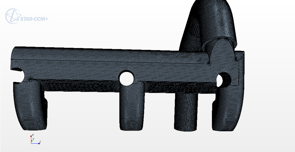 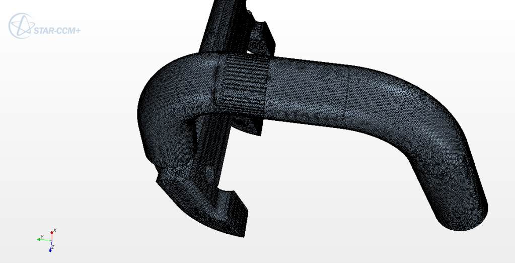 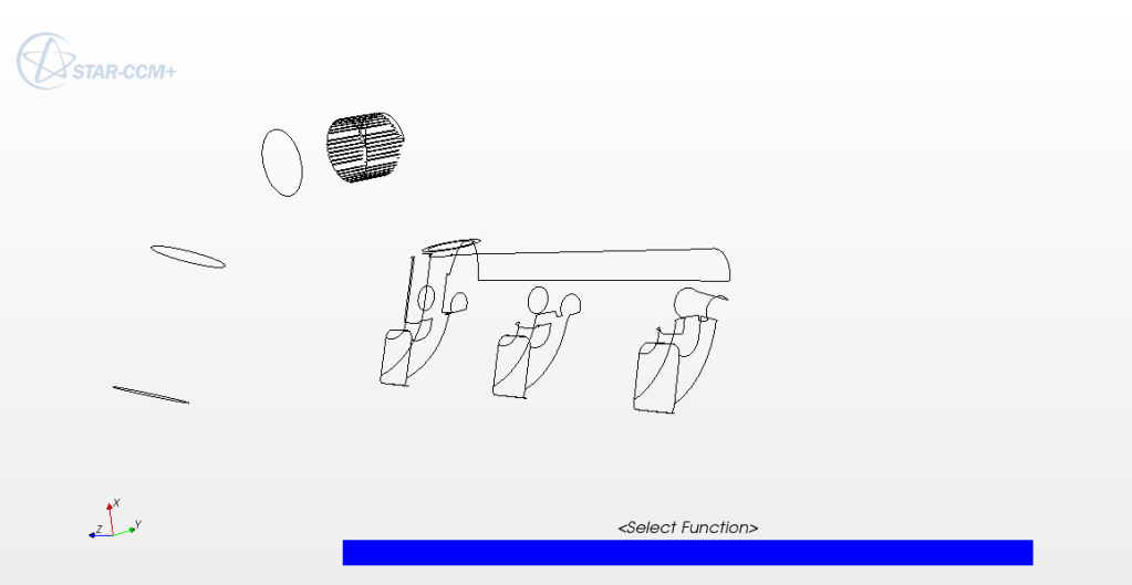
|
|
|
|
|
|
|
February 14, 2012, 03:45
|
|
#6 |
|
Member
aerosapien
Join Date: Sep 2010
Posts: 59
Rep Power: 15 |
take crossections along the required regions to get the scalar plots
regards www.aerosapien.blogspot.com |
|
|
|
|
|
|
February 14, 2012, 08:30
|
|
#7 |
|
Member
Join Date: Feb 2011
Location: DE-PB
Posts: 56
Rep Power: 15 |
First of all, if you want to display a scalar you have to run the simulation to get a result, just meshing isnt enough
") . .Then you have to choose parts for the scalar displayer and also an function (scalar) which should be displayed. You scalar scene is emty, no parts are selected and also no function is selected. I think you need basic knowledge about using ccm+. So please do some of the tutorials, this will help a lot. |
|
|
|
|
|
 |
|
|
 Similar Threads
|
||||
| Thread | Thread Starter | Forum | Replies | Last Post |
| [ICEM] Negative volume error in hybrid mesh | siw | ANSYS Meshing & Geometry | 4 | September 3, 2014 05:25 |
| 3D Hybrid Mesh Errors | DarrenC | ANSYS Meshing & Geometry | 11 | August 5, 2013 06:42 |
| [ICEM] Generating Mesh for STL Car in Windtunnel Simulation | tommymoose | ANSYS Meshing & Geometry | 48 | April 15, 2013 04:24 |
| [snappyHexMesh] snappyHexMesh won't work - zeros everywhere! | sc298 | OpenFOAM Meshing & Mesh Conversion | 2 | March 27, 2011 21:11 |
| Icemcfd 11: Loss of mesh from surface mesh option? | Joe | CFX | 2 | March 26, 2007 18:10 |
 Linear Mode


