|
|
|
[Sponsors] | ||||
[ICEM] Generating Mesh for STL Car in Windtunnel Simulation |
 |
|
|
LinkBack | Thread Tools | Search this Thread | Display Modes |
 December 1, 2009, 00:28
|
|
#41 |
|
Senior Member

Simon Pereira
Join Date: Mar 2009
Location: Ann Arbor, MI
Posts: 2,663
Blog Entries: 1
Rep Power: 47  |
I have a fun idea... have you ever tried the option to make the volume mesh conformal with a surface mesh?
Basically, the plan is to mesh this splitter separately to get a surface mesh... You load that surface mesh into your completed mesh. I think it could be a quad mesh, etc. but perhaps it works better with triangles. If it connects with the other surface mesh, merge nodes, sew or what ever it takes to connect it up... Don't worry about the volume mesh, but don't delete it either. The new splitter mesh will be independent of the volume mesh (passing thru it), but that is what the next step is for. Then go to "Edit mesh => Repair mesh -> Floodfill/Make Consistent". Change the toggle to "Make Volume Mesh consistent with surface mesh." You can run this on the whole model, but it may be easier to run it on a local subset of the tetras around your surface mesh. Hit apply. This will adjust the volume mesh to make it consistent with the surface mesh. I think it only works with tetras (probably not prisms), so hopefully this will be OK for you. You would then need to run prism again to get inflation on the splitter its self... This above plan has the advantage of leaving the mesh 99% identical between runs. However if it gives you any trouble (prisms in the way, etc.) you could regenerate the volume mesh... If you used the same settings for bottom up tetra and prism, you could also get a pretty similar result if you deleted the volume mesh, sewed in the new surface mesh and then ran the volume mesh steps over again... Of course the middle road of going back to your tetra mesh, making it consistent with your new surface mesh and then growing prisms is also an option, but I would only do that if your tetra mesh required a lot of interactive editing work beyond the automatic generation. |
|

|

|
|
|
December 15, 2009, 23:09
|
|
#42 |
|
New Member
Tom
Join Date: Jun 2009
Location: Cambridge, MA
Posts: 29
Rep Power: 16 |
That sounds like a very slick feature and I'm glad you explained how to use it. For several reasons I couldn't use it here, but its another tool I'll keep in mind for the future
 In order to stitch the splitter to the lip, I meshed the splitter with the same max. size elements as the lip. Stitching these was a bit tedious because the volume mesh needed to shift whenever I was pasting nodes and moving things around. This led to a little bit of a loading-lag or something with every move. When stiching hundreds of nodes it adds up. The other problem was that I also needed to stitch to my symmetry plane. My symmetry plane elements are larger (1 vs .25) than my splitter and lip and I wasn't sure how to go about stitching them together. I'll explain how I did end up doing it below. I created the splitter I wanted in CAD (NX) and brought it into ICEM. I then imported the lip geometry into the file. I moved the lip into place and slightly intersected the splitter. Then I created curves by intersection, and this left a nice curve for the nodes to align to on the splitter when I tetra-meshed. I meshed the same size as the lip so that connecting the nodes would be simple. Then I brought the meshed splitter into my project file and lined it up right. I deleted the volume mesh for the reasons listed above. Then I used merge nodes by tolerance and set it to 0.1. This took care of a majority of the stitching I needed to do. I used the diagnostics, found the remaining single edges, and stitched them manually. At this point the splitter was stitched up with the lip and all that remained was stitching it to the symmetry plane. I adjusted the surface mesh density in that area so it more closely matched the node spacing on the splitter and manually stitched the splitter to the symmetry plane. At this point I just delauny meshed and prism meshed the same way as before. I was hoping to kick-off a simulation tonight but it seems I have a problem after prism meshing. The splitter mesh is getting all distorted. Have you seen anything like this before and know how to fix it? |
|
|
|
|
|
|
December 16, 2009, 23:23
|
|
#43 |
|
Senior Member
Simon Pereira
Join Date: Mar 2009
Location: Ann Arbor, MI
Posts: 2,663
Blog Entries: 1
Rep Power: 47 |
I can guess...
Zoom in on that area where the mesh is distorted... In the display tree, right click on mesh and turn on the option for nodes as dots... This will color code the mesh... I am guessing that these splitter nodes will be blue (CYAN actually) meaning that they are not projected to the splitter surface. I am guessing that the smoother moved those nodes to improve the tetra mesh or something without regard for the surface because they were not surface projected... If this is the case, go back to some point before prism, either when the mesh was all tetra or even before that when you just had the surface mesh all sewn together. Under move nodes, you will find the options for associating the nodes, set these nodes to project to the nearest surface... (I am assuming that you have a surface ;^) |
|
|
|
|
|
|
December 20, 2009, 17:46
|
|
#44 |
|
New Member
Tom
Join Date: Jun 2009
Location: Cambridge, MA
Posts: 29
Rep Power: 16 |
The nodes show up as black, most likely because I don't have a surface for the splitter. I thought I wanted to surface mesh the splitter, export the .uns file, and import that mesh into the file? If that's the case, why would it bring the surface with it?
This was definitely occuring during the smoothing, so I resorted to moving them back into place (via XYZ move) afterwards. I then ran prism mesh and created a mesh for Fluent to read. When I try to read it in Fluent I get the following error - "Build Grid: Aborted due to critical error." I try again without moving the nodes back into place, just to see and I get the same error.  In a search, it seems that this error may occur when some zones aren't fully meshed? In a search, it seems that this error may occur when some zones aren't fully meshed?
|
|
|
|
|
|
|
December 21, 2009, 00:06
|
|
#45 |
|
Senior Member
Simon Pereira
Join Date: Mar 2009
Location: Ann Arbor, MI
Posts: 2,663
Blog Entries: 1
Rep Power: 47 |
Black or White means the same thing (can't we all just get along
 ), surface projected. If you back ground is lighter, surface projected nodes appear white and vice versa. ), surface projected. If you back ground is lighter, surface projected nodes appear white and vice versa.But having surface projected nodes and no surface to project to is the problem. You will need to import that surface geometry also (importing the mesh is not sufficient). Sorry I wasn't more clear about that. Go back to the mesh before things went bad (moving it back into place is tough when prisms are involved... actually any editing becomes tough when prisms are involved.) |
|
|
|
|
|
|
December 1, 2010, 13:00
|
|
#46 |
|
Senior Member
Simon Pereira
Join Date: Mar 2009
Location: Ann Arbor, MI
Posts: 2,663
Blog Entries: 1
Rep Power: 47 |
-----------------------------------------
Please help guide development at ANSYS by filling in these meshing surveys Public ANSYS ICEM CFD Users Survey This second one is more general (Gambit, TGrid and ANSYS Meshing users welcome)... CFD Online Users Survey |
|
|
|
|
|
|
March 14, 2011, 01:06
|
|
#47 |
|
New Member
Tom
Join Date: Jun 2009
Location: Cambridge, MA
Posts: 29
Rep Power: 16 |
I think I owe everyone that's helped here an update and a thank you. After successfully running several simulations to prove-out the concept and generate some qualitative data, my team and I proceeded to develop a prototype system and put together a presentation we were all proud of. In April we ended up winning our senior capstone design competition. It's funny that since we first started work, Ferrari unveiled the F455 Italia, featuring aeroelastic bits at the front bumper, and most recently Ford added active grill shutters to some of it's cars. Active-aero certainly seems to be gaining some attention.
The sponsor company (and good friends of mine) that I worked with on this for have moved forward with the idea. The first front-end active-aero setup was recently tested on a Ferrari F430 Challenge car in a 180mph rolling road wing tunnel, then at the track, and the results were fantastic. The F/R downforce balance achieved is unparalleled by any static system - both the wing angle and valve position were adjusted as a function of speed to keep the car handling neutral at all times. I'm currently working on making fit kits for different car models, so more than just F430 owners can enjoy  Here are some pics! 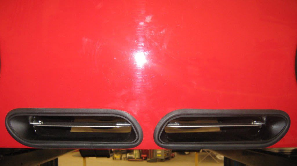 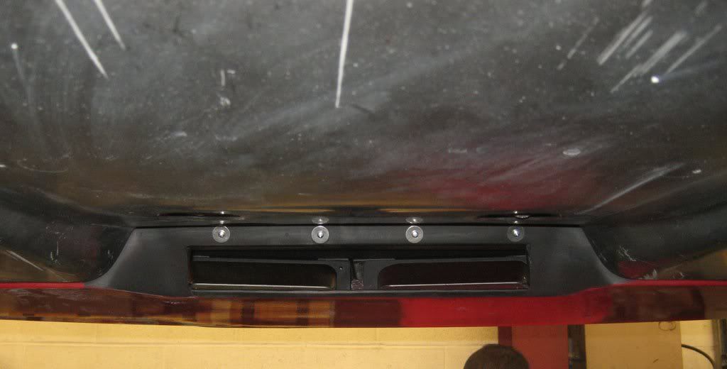 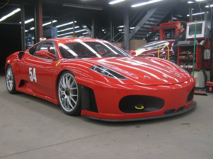 
|
|
|
|
|
|
|
April 15, 2013, 04:24
|
|
#49 |
|
New Member
Elaine
Join Date: Apr 2013
Location: China,Shanghai
Posts: 1
Rep Power: 0 |
Hi Simon, you have metioned 'the easiest way is to simply put things into parts and then turn off parts you don't need to look at any more... '. I want to know what software you use to put things into parts? ICEM or CATIA or something else? I have tried in ICEM but some faces will break into lots of parts which are in a mess.
|
|
|
|
|
|
|
| Tags |
| icem, mesh, stl, vehicle, windtunnel |
|
|
 Similar Threads
|
||||
| Thread | Thread Starter | Forum | Replies | Last Post |
| error in generating mesh in pro-am | Julian | Siemens | 3 | December 21, 2007 00:29 |
| Dynamic Mesh For car Racing | Sabre | FLUENT | 0 | July 3, 2007 08:33 |
| TGRID- Problem in generating Viscous Mesh | abhinit | FLUENT | 3 | January 8, 2007 08:48 |
| ground mesh of a car | Juan Manuel | Main CFD Forum | 0 | August 31, 2003 19:30 |
| unstructured vs. structured grids | Frank Muldoon | Main CFD Forum | 1 | January 5, 1999 10:09 |
 10Likes
 Linear Mode


