|
|
|
[Sponsors] | ||||
 May 6, 2013, 09:21
|
|
#1 |
|
Member
Billy
Join Date: Jan 2011
Posts: 31
Rep Power: 15  |
Hi,
I am trying to do a simple heat transfer problem in CFX. Have done something similar before in Fluent but would like to use CFX for this problem. Problem consists of a rectangle with an inlet (front face) and an outlet (top face). This represents a recess in the actual problem. Within the box is a heat source - represents a convective finned heating panel. I want to model varying velocities and monitor outlet temperature and speed. I have read many help guides and tutorials and followed a setup similar to the one described for the heating coil in the CFX tutorial pdf. Convergence is good but results shows no varying temperature across the a vertical place in the middle of the domain - I would expect high temperatures next to the heat source and low to high temperatures in the vertical plane. The temperature variable is constant. Probably something simple - any ideas greatly appreciated. |
|

|

|
|
|
May 6, 2013, 10:23
|
|
#2 |
|
Senior Member

Mr CFD
Join Date: Jun 2012
Location: Britain
Posts: 361
Rep Power: 14 |
Please post an image of your domain and boundaries.
In general for solid fluid heat transfer you need to understand physical time scales to aid better convergence. For example calculate the diffusion time scales for both fluid and solid domains. You'll see that they are very different. The point I'm making is don't set the same physical timestep for both solid and fluid domains unless off course they are the same! With regards to your results: double check your boundary conditions. Cfx and Fluent should give the same results if both setups are the same. |
|
|
|
|
|
|
May 6, 2013, 17:45
|
|
#3 |
|
Member
Billy
Join Date: Jan 2011
Posts: 31
Rep Power: 15 |
Was trying to get away with no pictures but I guess I should know better. Here is the problem domain and boundary conditions.
Geometry shaded 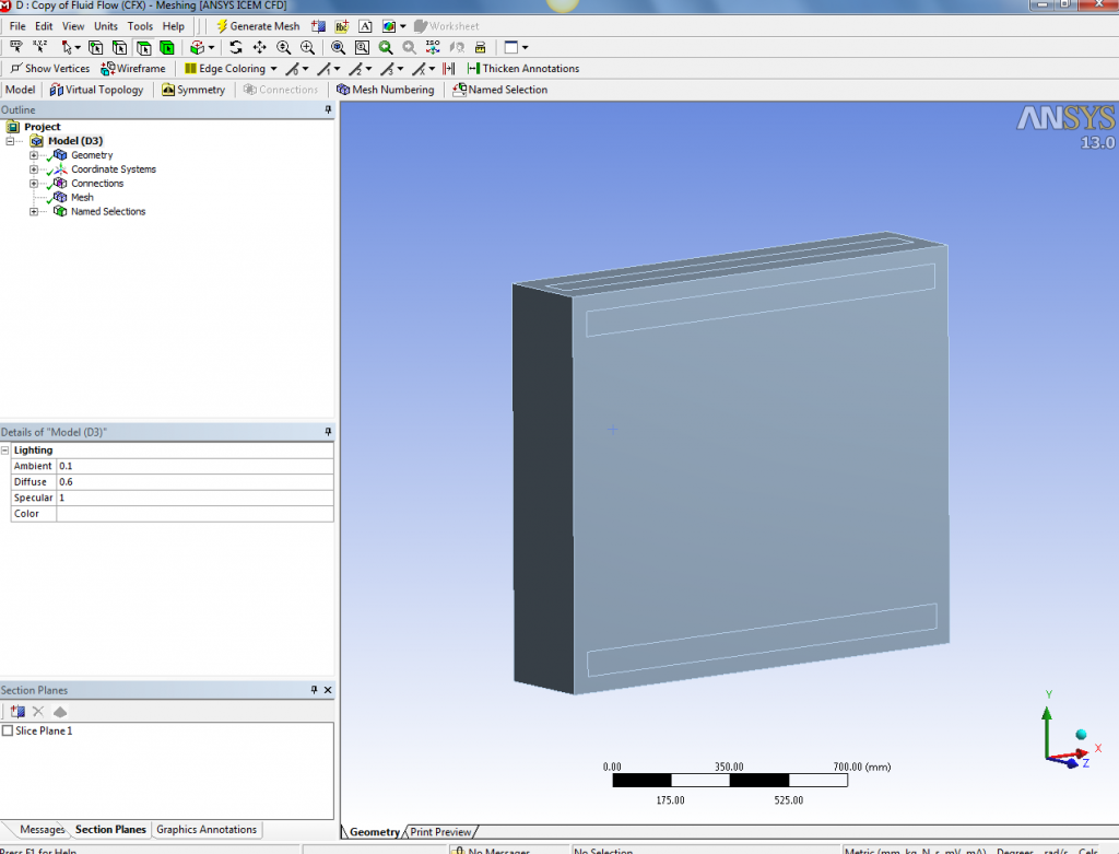 Geometry wireframe 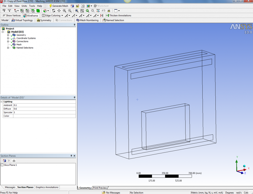 Boundary conditions and domain setup in CFX-Pre 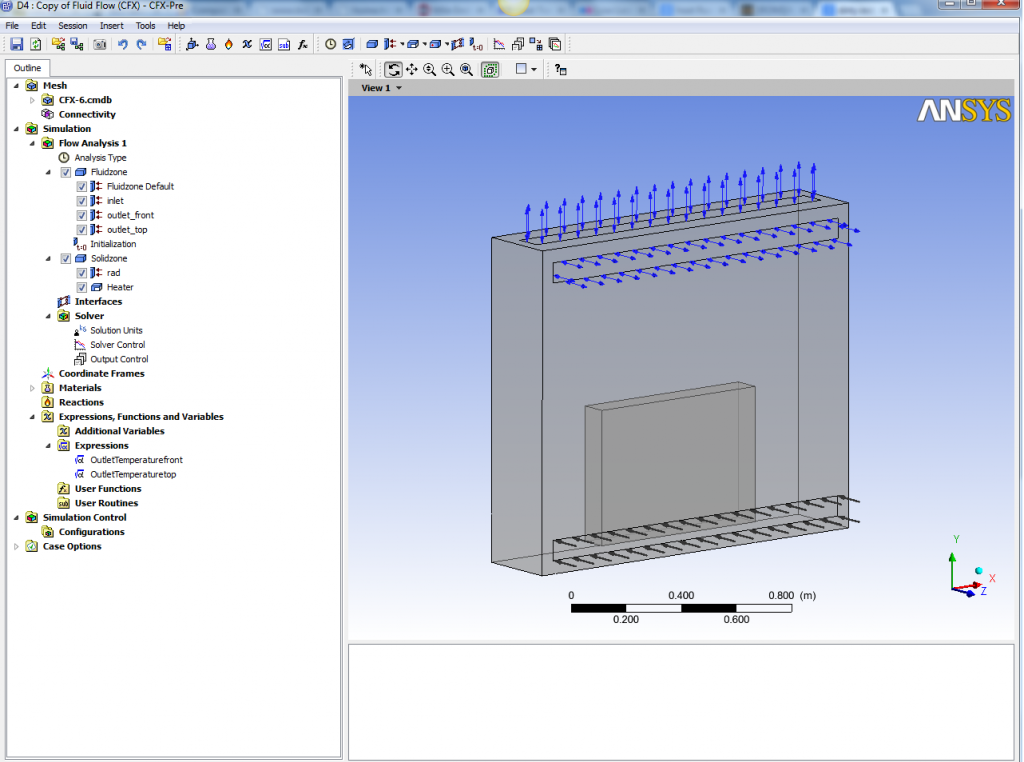 Results - constant temperature vertical plane with downward vectors (should be upward due to warmer air)  It is steady state model so time steps wouldnt come into it. Would they? Appreciate your help. |
|
|
|
|
|
|
May 6, 2013, 18:02
|
|
#4 |
|
Senior Member
Mr CFD
Join Date: Jun 2012
Location: Britain
Posts: 361
Rep Power: 14 |
CFX uses physical "false" timesteps for solution control in steady state simulations. In CFX pre check to see that you have physical timesteps enabled and not automatic timesteps. It should be under the menu where you set convergence controls such as the number of iterations etc. If you select physical timesteps you need to tell CFX what time steps you want to give it for all the domains that you have in your setup. Diffusion timescales in the solid can be estimated using the diffusion equation (I think it's thermal conductivity divided by the product of density and specific heat capacity - but double check this for yourself!)
Also in CFD post check to see you have the local variables selected and not the global variables. Also are you using any turbulence models? Does your mesh solve for pertinent flow features? I have done a similar simulation in the past with success. I'll try and dig it out tomorrow to see where you're going wrong. |
|
|
|
|
|
|
May 7, 2013, 17:11
|
|
#5 | |
|
Member
Billy
Join Date: Jan 2011
Posts: 31
Rep Power: 15 |
Quote:
I had automatic timescale selected in CFX-Pre. I am reading into the timescales for solid and fluid domains. Can you explain a bit more about why they are so important in this simulation? Even with automatic timescales selected, the solution converged (granted doesnt mean its correct), and would at least show something similar to what is expected rather completely different. Contour plot was set to local variables  Turbulence model is k-e. What do you mean by pertinent flow features? I have applied inflation at the walls but the mesh is fairly course - just wanted to get a working solution for increase run time. Any luck finding that model? Thanks for help. |
||
|
|
|
||
|
May 8, 2013, 11:41
|
|
#6 | |
|
Senior Member
Mr CFD
Join Date: Jun 2012
Location: Britain
Posts: 361
Rep Power: 14 |
Quote:
Don't get me wrong, automatic time scales are fine to begin with. However automatic time scales is just a guess, CFX is trying to predict the time scale associated with your flow. It might or might not converge within an acceptable wall clock time. By using physical "false" time stepping you're explicitly telling CFX what the time scales associated with your simulation is. This can lead to much better convergence and reduced simulation time. If you ran auto time scale vs physical time scale and allowed both to converge they will (or should!) both give the same results. However calculating physical time scales is very important in my opinion, as when you do calculate the physical time scales you are forced to understand the problem. Auto time scales don't allow this. Pertinent flow features refer to the areas where flow is important. E.g. if you're interested in what happens at the boundary layer you'll apply inflation with at least 10 nodes in the boundary layer thickness. If you don't care about what goes on in the bulk flow then you don't mesh that part as intensely as any other areas that you're interested in. Did you manage to fix your problem? |
||
|
|
|
||
|
May 8, 2013, 14:03
|
|
#7 |
|
Senior Member
OJ
Join Date: Apr 2012
Location: United Kindom
Posts: 473
Rep Power: 20 |
I think you haven't specified your heat source properly. Double check that. .
Also, is gravity switched on? I suppose if you have, and since the solution is steady, you are using Boussinesq's model for natural convection to model the density as a function of temperature, instead of solving it through transient NS equations. The only problem here is it is valid only for smaller temperature differences through out the domain. You are finding the convergence is easy because perhaps you haven't setup the BCs right. Natural convection problems are not always a piece of cake, when it comes to convergence. OJ |
|
|
|
|
|
|
May 8, 2013, 17:05
|
|
#8 | ||
|
Member
Billy
Join Date: Jan 2011
Posts: 31
Rep Power: 15 |
Quote:
plus I try to get down to the roots of the problem rather than just accepting an equation so I am taking my time. I can't get my head around the maths of how the CFX physical timescale acts as an under - relaxation factor (that's what I read).I am mainly interest in the bulk flow rather than flow at the wall - my points of interest are the temperature's and velocities at the outlets. I have assumed at this stage that turbulence at the wall will have minimal effect. Quote:
Gravity is on, solution is steady, but not sure where to set to use the Boussinesq's model - does this do it automatically. I am user air (ideal gas) within the fluid domain. How small is small - we should only be talking 10-20 deltaT. I thought this was ok for Boussinesq's. Completely agree my BC's are prob not right - just haven't found where is wrong. Interestingly enough I completed the CFX tutorial titled 'heat transfer from a heating coil' in order to try and fix solution and noticed the same result in a vertical plane apart from right next to the heat source. EDIT - just checked this and it shows a good temperature contour. My outlets are set as openings because of the guidance provided in that tutorial, i.e. coil (radiator in my case) will cause some re circulation at the exit. But actually the flow come back in through the outlets rather than from the inlet - see direction of velocity vectors. This points to me that the heat transfer if not happening correctly if at all. Sorry for the lengthy response - thanks for both your help. This is not something I do everyday, mainly self taught with a few training sessions here and there. |
|||
|
|
|
|||
|
May 9, 2013, 06:55
|
|
#9 |
|
Senior Member
OJ
Join Date: Apr 2012
Location: United Kindom
Posts: 473
Rep Power: 20 |
Boussinesq model kicks in automatically (I think) with gravity. The other way is to run the natural convection as a transient simulation and let the Solver calculate the density. But obviously this is expensive.
There aren't any guidelines in CFX manual about how small the temperature difference should be. But I guess 20 degrees in 300 degrees is less than 7%, should not be a problem. Few things: 1) Double check gravity direction - it should be 0, -g, 0 2) Are the streamlines colored by velocity or temperature? 3) Doublecheck if the contours are for temperature. OJ |
|
|
|
|
|
|
May 9, 2013, 07:50
|
|
#10 | |||
|
Senior Member
Mr CFD
Join Date: Jun 2012
Location: Britain
Posts: 361
Rep Power: 14 |
Quote:
Quote:
 << 1") Quote:
|
||||
|
|
|
||||
|
May 9, 2013, 09:30
|
|
#11 | |
|
Super Moderator
Glenn Horrocks
Join Date: Mar 2009
Location: Sydney, Australia
Posts: 17,703
Rep Power: 143 |
Quote:
Transient is irrelevant to the buoyancy options, I think what you meant to say was use a true compressibel gas model (like ideal gas) and then the gas density is naturally a function of temperature. And in my experience this is not too much more expensive than the buosinesq approach most of the time. |
||
|
|
|
||
|
May 9, 2013, 16:48
|
|
#12 |
|
Member
Billy
Join Date: Jan 2011
Posts: 31
Rep Power: 15 |
We're getting there gentleman! I am not sure what silly mistake I had made but there must have been. Checked, double checked and triple checked my BC's, made a few amendments by looking a couple of other tutorials and we have a temperature contour plot with variation!
So thanks for your help on this. Now on to physical time steps....two questions if I may as I am now attempting to refine the model. i estimate my physical timescales but the solution diverged. Two values I am unsure about that are referred to in the CFX documentation. l (ref section 14.4.1.3.3, eq. 14-2) = is a length scale associated with the vertical temperature gradient Lscale (ref section 1.9.2) = guidance here is a little misleading - refers to it as a solid time scale but then appears in an equation to calculate 'deltat', also referred to as the solid time scale Length scales have always baffled me a bit apart from the turbulence ones but this is probably because these are the most documented. @ghorrocks - It was my understand that when performing buoyancy driven flows, you have two options 1) Ideal gas and Boussinesq model or 2) Compressible fluid and calculating the density as a function of properties during the simulation - did I understand this wrong? My model in CFX currently uses 'Air Ideal Gas' Thanks guys! |
|
|
|
|
|
|
May 9, 2013, 18:04
|
|
#13 |
|
Super Moderator
Glenn Horrocks
Join Date: Mar 2009
Location: Sydney, Australia
Posts: 17,703
Rep Power: 143 |
Length scale means a length characteristic of the flow. In pipe flow that could be the pipe diameter, in boundary layer development it is length along the surface. In this case I would consider something like the height of the hot wall.
The two buoyancy options are: * Boussinesq, which uses a constant density (that is incompressible) fluid model and imposes the buoyancy as a source term * Fully compressible flow where density is a function of temperature. If you are using ideal gas then you are using the second option. But to use ideal gas you need to select the ideal gas material AND have a total energy heat equation. If you just use the thermal heat equation you have the first option. |
|
|
|
|
|
|
May 9, 2013, 18:16
|
|
#14 | ||||
|
Senior Member
OJ
Join Date: Apr 2012
Location: United Kindom
Posts: 473
Rep Power: 20 |
Quote:
Quote:
Quote:
Quote:
|
|||||
|
|
|
|||||
|
January 11, 2021, 12:12
|
|
#15 | |
|
New Member
Join Date: Aug 2019
Posts: 1
Rep Power: 0 |
Quote:
|
||
|
|
|
||
|
January 11, 2021, 19:19
|
|
#16 |
|
Super Moderator
Glenn Horrocks
Join Date: Mar 2009
Location: Sydney, Australia
Posts: 17,703
Rep Power: 143 |
If you read the documentation (Theory manual, section 1.2.1.4) it explains that the Thermal Energy equation is "... appropriate for liquids, where variable-density effects are negligible.", and that if variable density effects are important then you should use total energy.
Both Total Energy and Thermal Energy approaches can apply the work due to viscous stresses, that is a different thing.
__________________
Note: I do not answer CFD questions by PM. CFD questions should be posted on the forum. |
|
|
|
|
|
 |
|
|
 Similar Threads
|
||||
| Thread | Thread Starter | Forum | Replies | Last Post |
| which solver (tutorial) is for heat transfer between fluid and solid? | mxylondon | OpenFOAM | 3 | December 14, 2012 19:54 |
| Heat Flux at Internal walls or Fluid Solid Interface | Mahi | CFX | 3 | October 1, 2012 02:18 |
| Solid / Fluid Heat Transfer | Koranten | FLUENT | 3 | March 19, 2011 07:21 |
| modeling heat transfer betwwen fluid and solid | Al Mazdeh | CFX | 0 | March 13, 2008 10:35 |
| Water vapour condensation in CFX-5.7.1 | hdj | CFX | 1 | November 27, 2005 07:15 |
 2Likes

 Linear Mode


