|
|
|
[Sponsors] | ||||
 April 28, 2016, 03:43
|
|
#1 |
|
Member
ngoc tran bao
Join Date: Jan 2016
Posts: 35
Rep Power: 10  |
Dear all,
I'm carrying out a pump simulation and try to plot velocity vector at mid plane of impeller passage in order to visualize jet-wake structure. This is the phenomenon which occurs near suction side of impeller blade due to low velocity flow. However, the result observed from simulation is different from theoretic researches. The low velocity region should be appeared in suction side of blade, but in my case it is on pressure side (as in enclosed picture). I do not understand why my simulation is reverse. Do my set up in CFX-pre have somethings wrong? Can anyone give me some points? Thank you for reading my thread. Here is my CEL  ownload URL:http://www.gigasize.com/get/6zxwp7fz0pc ownload URL:http://www.gigasize.com/get/6zxwp7fz0pc
|
|

|

|
|
|
April 28, 2016, 04:29
|
|
#2 |
|
Member
Join Date: Nov 2013
Posts: 57
Rep Power: 12 |
Hello,
Please mention your boundary condition and all settings you did in CFX-pre. |
|
|
|
|
|
|
April 28, 2016, 07:03
|
|
#3 |
|
Senior Member
Join Date: Jun 2009
Posts: 1,803
Rep Power: 32 |
Have you looked into the plots for Velocity in Stn Frame ?
|
|
|
|
|
|
|
April 28, 2016, 07:43
|
|
#4 |
|
Member
ngoc tran bao
Join Date: Jan 2016
Posts: 35
Rep Power: 10 |
Hi Lirezame,
As for BC, I set total Pressure at Inlet = 0.14 Mpa; Mass Flow rate at Outlet = 80 m3/h; Rotation = -1750 RPM (Z axis) Smooth wall for all suction, discharge walls; Reference Pressure =0 atm; Physical time step =1/W. You can look for detail in my CEL in the thread. |
|
|
|
|
|
|
April 28, 2016, 07:45
|
|
#5 |
|
Member
Join Date: Nov 2013
Posts: 57
Rep Power: 12 |
can you put a figure of your CEL? the link does not work properly.
|
|
|
|
|
|
|
April 28, 2016, 07:50
|
|
#6 |
|
Member
ngoc tran bao
Join Date: Jan 2016
Posts: 35
Rep Power: 10 |
Hi Opaque, thank for your suggest.
I get the same result with velocity in stationary frame. Like this picture: 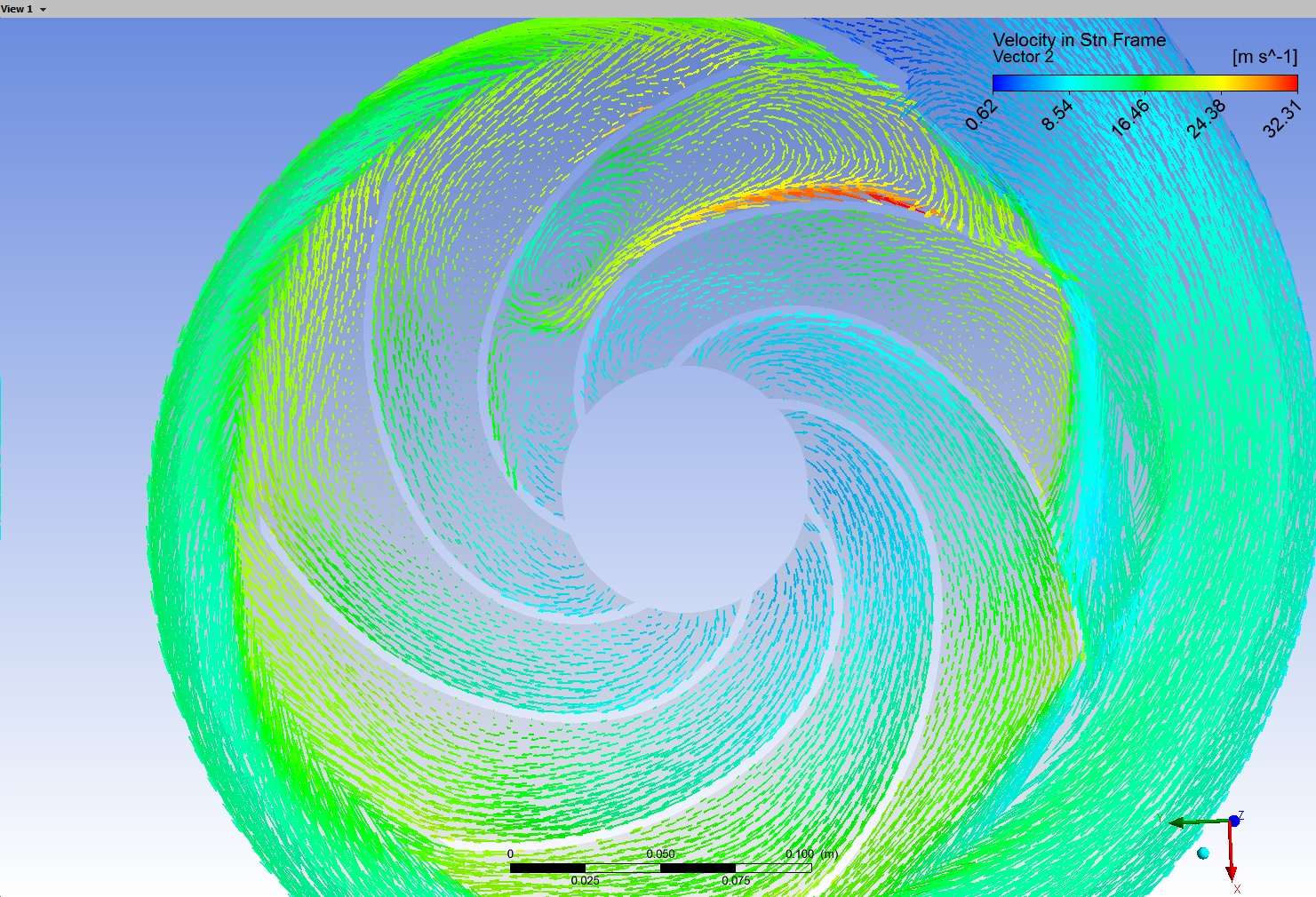
|
|
|
|
|
|
|
April 28, 2016, 07:58
|
|
#7 |
|
Member
ngoc tran bao
Join Date: Jan 2016
Posts: 35
Rep Power: 10 |
This is CEL of my simulation, can you help me to take a look. I hope it's not too long, thank you.
ANALYSIS TYPE: Option = Steady State EXTERNAL SOLVER COUPLING: Option = None END END DOMAIN: Discharge Coord Frame = Coord 0 Domain Type = Fluid Location = DISCHARGE_FLUID_1_1_SOLID BOUNDARY: Discharge_wall Boundary Type = WALL Location = DISCHARGE_WALL BOUNDARY CONDITIONS: MASS AND MOMENTUM: Option = No Slip Wall END WALL ROUGHNESS: Option = Smooth Wall END END END BOUNDARY: Impeller_discharge Side 2 Boundary Type = INTERFACE Location = DISCHARGE_IN BOUNDARY CONDITIONS: MASS AND MOMENTUM: Option = Conservative Interface Flux END TURBULENCE: Option = Conservative Interface Flux END END END BOUNDARY: Outlet Boundary Type = OUTLET Location = OUTLET BOUNDARY CONDITIONS: FLOW REGIME: Option = Subsonic END MASS AND MOMENTUM: Mass Flow Rate = 17.0666667 [kg s^-1] Option = Mass Flow Rate END END END DOMAIN MODELS: BUOYANCY MODEL: Option = Non Buoyant END DOMAIN MOTION: Option = Stationary END MESH DEFORMATION: Option = None END REFERENCE PRESSURE: Reference Pressure = 0 [atm] END END FLUID DEFINITION: Fluid 1 Material = Water Option = Material Library MORPHOLOGY: Option = Continuous Fluid END END FLUID MODELS: COMBUSTION MODEL: Option = None END HEAT TRANSFER MODEL: Fluid Temperature = 25 [C] Option = Isothermal END THERMAL RADIATION MODEL: Option = None END TURBULENCE MODEL: Option = k epsilon END TURBULENT WALL FUNCTIONS: Option = Scalable END END END DOMAIN: Impeller Coord Frame = Coord 0 Domain Type = Fluid Location = ROTATING_FLUID_CHUAN_1_1_SOLID BOUNDARY: Blade Boundary Type = WALL Frame Type = Rotating Location = BLADES,HUB,SHROUND BOUNDARY CONDITIONS: MASS AND MOMENTUM: Option = No Slip Wall END WALL ROUGHNESS: Option = Smooth Wall END END END BOUNDARY: Impeller_discharge Side 1 Boundary Type = INTERFACE Location = IMPELLER_OUT BOUNDARY CONDITIONS: MASS AND MOMENTUM: Option = Conservative Interface Flux END TURBULENCE: Option = Conservative Interface Flux END END END BOUNDARY: Impeller_wall Boundary Type = WALL Frame Type = Rotating Location = IMPELLER_WALL BOUNDARY CONDITIONS: MASS AND MOMENTUM: Option = No Slip Wall WALL VELOCITY: Option = Counter Rotating Wall END END WALL ROUGHNESS: Option = Smooth Wall END END END BOUNDARY: Intake_Impeller Side 2 Boundary Type = INTERFACE Location = IMPELLER_IN BOUNDARY CONDITIONS: MASS AND MOMENTUM: Option = Conservative Interface Flux END TURBULENCE: Option = Conservative Interface Flux END END END DOMAIN MODELS: BUOYANCY MODEL: Option = Non Buoyant END DOMAIN MOTION: Alternate Rotation Model = On Angular Velocity = -1750 [rev min^-1] Option = Rotating AXIS DEFINITION: Option = Coordinate Axis Rotation Axis = Coord 0.3 END END MESH DEFORMATION: Option = None END REFERENCE PRESSURE: Reference Pressure = 0 [atm] END END FLUID DEFINITION: Fluid 1 Material = Water Option = Material Library MORPHOLOGY: Option = Continuous Fluid END END FLUID MODELS: COMBUSTION MODEL: Option = None END HEAT TRANSFER MODEL: Fluid Temperature = 25 [C] Option = Isothermal END THERMAL RADIATION MODEL: Option = None END TURBULENCE MODEL: Option = k epsilon END TURBULENT WALL FUNCTIONS: Option = Scalable END END END DOMAIN: suction Coord Frame = Coord 0 Domain Type = Fluid Location = INTAKE_BULKHEAD_EXTEND_1_1_SOL BOUNDARY: Inlet Boundary Type = INLET Location = INLET BOUNDARY CONDITIONS: FLOW DIRECTION: Option = Normal to Boundary Condition END FLOW REGIME: Option = Subsonic END MASS AND MOMENTUM: Option = Total Pressure Relative Pressure = 0.14 [MPa] END TURBULENCE: Option = Low Intensity and Eddy Viscosity Ratio END END END BOUNDARY: Intake_Impeller Side 1 1 Boundary Type = INTERFACE Location = INTAKE_OUT BOUNDARY CONDITIONS: MASS AND MOMENTUM: Option = Conservative Interface Flux END TURBULENCE: Option = Conservative Interface Flux END END END BOUNDARY: Intake_wall Boundary Type = WALL Location = INTAKE_WALL BOUNDARY CONDITIONS: MASS AND MOMENTUM: Option = No Slip Wall END WALL ROUGHNESS: Option = Smooth Wall END END END DOMAIN MODELS: BUOYANCY MODEL: Option = Non Buoyant END DOMAIN MOTION: Option = Stationary END MESH DEFORMATION: Option = None END REFERENCE PRESSURE: Reference Pressure = 0 [atm] END END FLUID DEFINITION: Fluid 1 Material = Water Option = Material Library MORPHOLOGY: Option = Continuous Fluid END END FLUID MODELS: COMBUSTION MODEL: Option = None END HEAT TRANSFER MODEL: Fluid Temperature = 25 [C] Option = Isothermal END THERMAL RADIATION MODEL: Option = None END TURBULENCE MODEL: Option = k epsilon END TURBULENT WALL FUNCTIONS: Option = Scalable END END END DOMAIN INTERFACE: Impeller_discharge Boundary List1 = Impeller_discharge Side 1 Boundary List2 = Impeller_discharge Side 2 Interface Type = Fluid Fluid INTERFACE MODELS: Option = General Connection FRAME CHANGE: Option = Frozen Rotor END MASS AND MOMENTUM: Option = Conservative Interface Flux MOMENTUM INTERFACE MODEL: Option = None END END PITCH CHANGE: Option = Specified Pitch Angles Pitch Angle Side1 = 360 [degree] Pitch Angle Side2 = 360 [degree] END END MESH CONNECTION: Option = GGI END END DOMAIN INTERFACE: Suction_Impeller Boundary List1 = Intake_Impeller Side 1 1 Boundary List2 = Intake_Impeller Side 2 Interface Type = Fluid Fluid INTERFACE MODELS: Option = General Connection FRAME CHANGE: Option = Frozen Rotor END MASS AND MOMENTUM: Option = Conservative Interface Flux MOMENTUM INTERFACE MODEL: Option = None END END PITCH CHANGE: Option = Specified Pitch Angles Pitch Angle Side1 = 360 [degree] Pitch Angle Side2 = 360 [degree] END END MESH CONNECTION: Option = GGI END END OUTPUT CONTROL: MONITOR OBJECTS: MONITOR BALANCES: Option = Full END MONITOR FORCES: Option = Full END MONITOR PARTICLES: Option = Full END MONITOR POINT: P outlet Coord Frame = Coord 0 Expression Value = areaAve(Pressure)@Outlet Option = Expression END MONITOR POINT: Torque Coord Frame = Coord 0 Expression Value = torque_z@Blade Option = Expression END MONITOR POINT: Vel outlet Coord Frame = Coord 0 Expression Value = areaAve(Velocity in Stn Frame)@Outlet Option = Expression END MONITOR RESIDUALS: Option = Full END MONITOR TOTALS: Option = Full END END RESULTS: File Compression Level = Default Option = Standard END END SOLVER CONTROL: Turbulence Numerics = First Order ADVECTION SCHEME: Option = High Resolution END CONVERGENCE CONTROL: Maximum Number of Iterations = 2000 Minimum Number of Iterations = 1 Physical Timescale = 0.01 [s] Timescale Control = Physical Timescale END CONVERGENCE CRITERIA: Residual Target = 1e-04 Residual Type = RMS END DYNAMIC MODEL CONTROL: Global Dynamic Model Control = On END END END |
|
|
|
|
|
|
April 28, 2016, 08:03
|
|
#8 |
|
Member
Join Date: Nov 2013
Posts: 57
Rep Power: 12 |
did you get fully converged calculation? according to the residual target which is a bit large and your time step, maybe your result has not converged yet.
what were your convergence criteria? |
|
|
|
|
|
|
April 28, 2016, 08:11
|
|
#9 |
|
Member
ngoc tran bao
Join Date: Jan 2016
Posts: 35
Rep Power: 10 |
Dear Alirezame,
For this simulation, I got the convergence. You mean the convergence criteria of 10^-4 is large, so I need to reduce it to somewhere around 10^-5 in order to get higher accuracy? May be, you're right, but in most of the paper I have read, researchers often used a convergence criteria of 10^-4 and I think it is enough. |
|
|
|
|
|
|
April 28, 2016, 08:18
|
|
#10 |
|
Member
Join Date: Nov 2013
Posts: 57
Rep Power: 12 |
''Residual Target = 1e-04'' it means that once one of the residuals reaches this amount, solver stops and gives to the convergence notification even before the maximum number of iteration. In most of cases, RMS P-Mass comes lower than other RMS residuals and this affects the accuracy by selecting 10^-4 as the residual target. in my opinion, decrease the residual target to 10^-8 o even lower and check the imbalance of all zones (as you know it should be too close to zero and stable) and also stability of the efficiency instead of residual checks.
other settings seem correct in my opinion. |
|
|
|
|
|
|
April 28, 2016, 08:41
|
|
#11 |
|
Member
ngoc tran bao
Join Date: Jan 2016
Posts: 35
Rep Power: 10 |
Thanks, I have never used such a low convergence target of 10^-8. I will try to reduce it as you suggest, and will post result if it work. Thank you, again.

|
|
|
|
|
|
|
April 28, 2016, 08:41
|
|
#12 | ||
|
Senior Member
Maxim
Join Date: Aug 2015
Location: Germany
Posts: 415
Rep Power: 12 |
Quote:
I always use MAX residuals, but I don't think RMS is different. I also don't think 10^-4 is the culprit here... Quote:
Are your imbalances under 1%? I would not use a specific mass flow rate at the outlet. The impeller is supposed to create the mass flow and not the boundary conditions. |
|||
|
|
|
|||
|
April 28, 2016, 22:20
|
|
#13 |
|
Member
ngoc tran bao
Join Date: Jan 2016
Posts: 35
Rep Power: 10 |
Maxim: I do not really understand the terminology "imbalance" you referred to. As for Outlet BC, many tutorials guide learners to set Flow rate at Outlet. It is more seasonable than Pressure. So I dont think it make me get trouble. In your opinion, what should we set for outlet BC?
|
|
|
|
|
|
|
April 29, 2016, 02:07
|
|
#14 |
|
Super Moderator
Glenn Horrocks
Join Date: Mar 2009
Location: Sydney, Australia
Posts: 17,700
Rep Power: 143 |
MAX vs RMS: The equation residuals are calculated at each integration point. Over the entire domain you can take either the RMS or MAX value as your convergence criteria. Obviously RMS is looser, and will allow a small number of points to have large residuals but still achieve convergence. MAX means that no integration point exceeds the criteria so is much stricter. MAX can be hard to use in poor quality meshes as the residuals in the poor mesh regions will be much higher than everywhere else.
1e-4: Yes, this is guide to convergence but only a guide. You should do a sensitivity check to establish what criteria you need for adequate convergence. Imbalances: This looks at the global conservation of things like mass, momentum and heat. For instance the total mass flowing into the domain must equal the mass flowing out in steady state; or the momentum across a domain must sum to zero and so on. For simulation where these global balances are important including imbalances in your convergence criteria is a good idea (eg CHT simulations). But flow over an airfoil is an example of a flow where it probably is not required as the residuals are a good guide to convergence. Which Boundary Condition: You should use boundary conditions which match what you know about the flow. If you know the flow rate then use a velocity, If you know the pressure then use a pressure boundary. If you don't know anything then you can't put a boundary there and must move the boundary to somewhere where you do know the flow conditions. |
|
|
|
|
|
|
April 29, 2016, 04:01
|
|
#15 |
|
Member
ngoc tran bao
Join Date: Jan 2016
Posts: 35
Rep Power: 10 |
Ghorrocks, thank you Sir, I learn a lot from your reply.
As for BC: I have already known the total pressure at Inlet, Head and Q design of the pump, now I try to investigate vector velocity of flow field in different flow rates (both design and off-design condition). That's the reason why I set Flow rate for Outlet BC and vary it for each circumstance. As for imbalance: as I understand, in my case if I put an flow rate at outlet, after getting the solution I need to check flow rate at Inlet to compare it. Is this right? I have done this, the discrepancy is quite small, about 0.0245%. What I wonder in my result is that, the low velocity region should be appeared in suction side of blade, but in my case it is on pressure side. Can you give me some ideas about this abnormal phenomenon? |
|
|
|
|
|
|
April 29, 2016, 04:16
|
|
#16 | |
|
Senior Member
Maxim
Join Date: Aug 2015
Location: Germany
Posts: 415
Rep Power: 12 |
Quote:
|
||
|
|
|
||
|
April 29, 2016, 05:03
|
|
#17 | |
|
Member
ngoc tran bao
Join Date: Jan 2016
Posts: 35
Rep Power: 10 |
Quote:

|
||
|
|
|
||
|
April 29, 2016, 12:36
|
|
#18 |
|
Senior Member
Join Date: Jun 2009
Posts: 174
Rep Power: 16 |
The tolerance of 1e-4 would be OK if not so accurate solution is wanted for check. From what view do you say "Low velocity happens on the pressure side" ??? I do not get it.
|
|
|
|
|
|
|
May 2, 2016, 10:45
|
|
#19 | |
|
Member
ngoc tran bao
Join Date: Jan 2016
Posts: 35
Rep Power: 10 |
Quote:
|
||
|
|
|
||
|
May 2, 2016, 10:54
|
|
#20 |
|
Member
ngoc tran bao
Join Date: Jan 2016
Posts: 35
Rep Power: 10 |
Maxim, I think I get high imbalance in this circumstance because I carry out the simulation at off-design condition ( Q=0.6 Qdesign). Another simulation at design condition gives me quite low imbalance, all imbalances are under 1%. However, the abnormal phenomenon of low velocity flow field still exists. I think there is something wrong in setup parameters but I can not find it.
|
|
|
|
|
|
 |
|
|
 Similar Threads
|
||||
| Thread | Thread Starter | Forum | Replies | Last Post |
| [Help!] impeller torque calculation: pressure and viscous moments | ghost82 | Main CFD Forum | 1 | March 27, 2014 02:37 |
| how to compute relative velocity from absolute? | spk | Main CFD Forum | 3 | July 9, 2010 08:42 |
| Strange Velocity in impeller of MRFSimpleFOAM | waynezw0618 | OpenFOAM Running, Solving & CFD | 50 | December 21, 2009 09:45 |
| Velocity in Porous medium : HELP! HELP! HELP! | Kali Sanjay | Phoenics | 0 | November 6, 2006 06:10 |
| what the result is negatif pressure at inlet | chong chee nan | FLUENT | 0 | December 29, 2001 05:13 |
 2Likes
 Linear Mode


