|
|
|
[Sponsors] | ||||
Problem with wall heat transfer coefficient during drilling |
 |
|
|
LinkBack | Thread Tools | Search this Thread | Display Modes |
 December 11, 2016, 18:15
|
|
#1 |
|
New Member
Paul
Join Date: Dec 2016
Posts: 7
Rep Power: 9  |
Hello everyone!
Could you be kind enough to tell me how to make like that? Maybe someone has a tutorial on how to do it? https://www.youtube.com/watch?v=KslKsdfeWJw |
|

|

|
|
|
December 12, 2016, 04:16
|
|
#2 |
|
Super Moderator
Glenn Horrocks
Join Date: Mar 2009
Location: Sydney, Australia
Posts: 17,703
Rep Power: 143 |
The tutorials which come with CFX are a good place to start. Have a look on the ANSYS customer webpage, or the tutorials provided with CFX.
|
|
|
|
|
|
|
December 12, 2016, 14:47
|
|
#3 |
|
New Member
Paul
Join Date: Dec 2016
Posts: 7
Rep Power: 9 |
What am I doing wrong?
My setup is like this: Air temp = 20*C Drill temp = 150*C Drill speed = 1000 rev/min^-1 I have to calculate the heat flow.. https://drive.google.com/open?id=0B7...mlQVDBGbXdqWkE Last edited by Paul666; December 13, 2016 at 07:55. |
|
|
|
|
|
|
December 12, 2016, 16:32
|
|
#4 |
|
Super Moderator
Glenn Horrocks
Join Date: Mar 2009
Location: Sydney, Australia
Posts: 17,703
Rep Power: 143 |
Air pressure = 1000 MPa? Are you sure on that one? Which planet are you running this wind turbine on?
And what has a drill got to do with a wind turbine? |
|
|
|
|
|
|
December 12, 2016, 17:47
|
|
#5 |
|
Member
turbo4life
Join Date: Nov 2016
Posts: 41
Rep Power: 9 |
Is this an oil drill powered by a wind turbine? I can't understand your model.
|
|
|
|
|
|
|
December 13, 2016, 08:22
|
|
#6 |
|
New Member
Paul
Join Date: Dec 2016
Posts: 7
Rep Power: 9 |
haha okej, let's start from the beginning.
I try to give the rotation of the drill in the Z axis at a speed of 8,000 [rev / min ^ -1]. When Defining the speed and the rotation axis shows me of the message: In Analysis 'Flow Analysis 1' - Domain 'Air: If a solid has motion set and it is connected to a stationary fluid domain, a moving wall velocity boundary condition must be specified on the fluid solid interface. However, I do not know what exactly it. Any ideas? 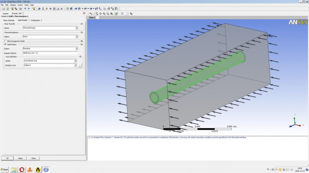 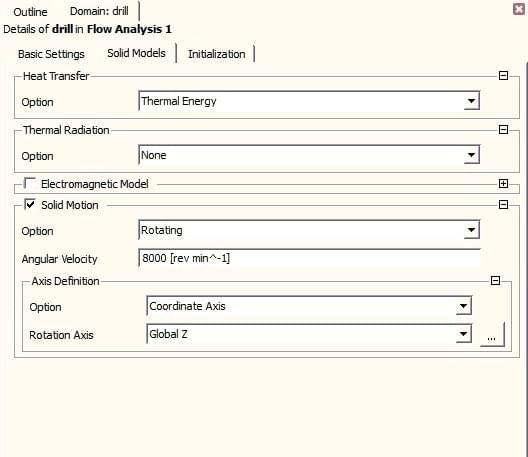 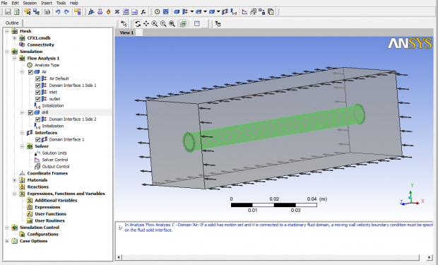
|
|
|
|
|
|
|
December 13, 2016, 16:31
|
|
#7 | |
|
Super Moderator
Glenn Horrocks
Join Date: Mar 2009
Location: Sydney, Australia
Posts: 17,703
Rep Power: 143 |
Quote:
|
||
|
|
|
||
|
December 14, 2016, 01:51
|
|
#8 |
|
New Member
Paul
Join Date: Dec 2016
Posts: 7
Rep Power: 9 |
Sorry for the confusion, please administrator to change the topic to "Problem with wall heat transfer coefficient during drilling"
My job is to: I must modeled a simplified model of the drill and then calculate the wall heat transfer coefficient during drilling. The Drill bit is rotated at 8,000[rev / min] in Z axis and the initial temperature is 150 ° C. Around the drill is air at a temperature of 25 ° C. I used the function enclosure to determine the area in which they conducted research. I have problem with the giving rotation Drills. I tried to do as above in the pictures. However, not working as it should. I want to use the results also line speed to show how the air behaves around the drills. |
|
|
|
|
|
|
December 14, 2016, 05:22
|
|
#9 |
|
Super Moderator
Glenn Horrocks
Join Date: Mar 2009
Location: Sydney, Australia
Posts: 17,703
Rep Power: 143 |
I have changed the title of the thread. But before we can answer your question we need to know much more about what you are trying to do.
Is the drill just rotating in open air? Or is it in a hole and performing the drilling action? Do you just want the HTC? Or do you want the cooling curve of the drill? Or are you interested in what the air flow does around the drill? Are there any other heat sources/sinks acting on the drill? Maybe heat from friction, or a coolant, or just ambient air? Do you need to know the temperature profile inside the drill? |
|
|
|
|
|
|
December 14, 2016, 05:34
|
|
#10 |
|
New Member
Paul
Join Date: Dec 2016
Posts: 7
Rep Power: 9 |
Thank you for changing the theard.
1. Yes, the drill is rotated in open air. 2. Yes, I want to see speed lines. As the air flows around the rotating drill. 3. No, there is only ambient air, which has 25 * C 4. No, only on the surface of the drill. I can insert more screenshots of the module "setup" or send whole file with the program. |
|
|
|
|
|
|
December 14, 2016, 05:41
|
|
#11 |
|
Super Moderator
Glenn Horrocks
Join Date: Mar 2009
Location: Sydney, Australia
Posts: 17,703
Rep Power: 143 |
What are speed lines? Do you mean stream lines?
Can the drill be assumed at constant temperature? What is the ambient air doing? Does it have a cross flow? Do you expect it to form a buoyant plume? |
|
|
|
|
|
|
December 14, 2016, 05:47
|
|
#12 |
|
New Member
Paul
Join Date: Dec 2016
Posts: 7
Rep Power: 9 |
1. Yes, I mean stream lines.
2. Yes, we can assume the drill at a constant temperature (150*C) 3. Cross flow |
|
|
|
|
|
|
December 14, 2016, 05:53
|
|
#13 |
|
Super Moderator
Glenn Horrocks
Join Date: Mar 2009
Location: Sydney, Australia
Posts: 17,703
Rep Power: 143 |
OK, almost there. Just a last question:
How strong is the cross flow? |
|
|
|
|
|
|
December 14, 2016, 06:17
|
|
#14 |
|
Super Moderator
Glenn Horrocks
Join Date: Mar 2009
Location: Sydney, Australia
Posts: 17,703
Rep Power: 143 |
While you are answering the cross flow strength question, I can make the following suggestions:
As the drill temperature is known then you do not need to model it. So do not model the drill as a solid body. The drill should be modelled as a rotating frame of reference with the drill being a cavity inside the rotating frame of reference - just like what is commonly done in turbomachinery simulations. Have a look in the CFX tutorials for examples of this. You can probably model the rotating frame of reference as a frozen rotor. This will mean you can model the drill with a steady state simulation which will dramatically simplify things. The strength of the cross flow will determine whether buoyancy is necessary or not. |
|
|
|
|
|
|
|
|
 Similar Threads
|
||||
| Thread | Thread Starter | Forum | Replies | Last Post |
| Difficulty In Setting Boundary Conditions | Moinul Haque | CFX | 4 | November 25, 2014 17:30 |
| Radiation interface | hinca | CFX | 15 | January 26, 2014 17:11 |
| Thin Wall Heat Transfer BC for rhoSimpleFoam | swahono | OpenFOAM Running, Solving & CFD | 12 | October 4, 2013 11:49 |
| strange wall heat transfer coefficient | Lea | FLUENT | 2 | December 18, 2012 09:23 |
| Wall heat transfer coefficient (HTC) problem | Mohamed khamis | CFX | 1 | January 15, 2010 23:12 |
 Linear Mode


