|
|
|
[Sponsors] | ||||
 June 9, 2007, 11:15
|
|
#1 |
|
Guest
Posts: n/a
|
hi all:
iam making an airfoil simulation in ansys cfx to predict the lift and drag coefficients for the 2d airfoil and i would like to ask if i want to change the angle of attack from zero value, should i change the slope of the inlet domain or just change the inelt velocity values at x and y direction? secondly, how to test a 2d airfoil in ansys cfx rather than 3d airfoil( with finite thickness)? thanks |
|

|
||
|
June 9, 2007, 11:40
|
|
#2 |
|
Guest
Posts: n/a
|
Both of these questions have been dealt with ... use this search function.
|
|
|
|
||
|
June 11, 2007, 01:33
|
|
#3 |
|
Guest
Posts: n/a
|
HI..
u are correct hammam, for AOA changet the velocity components at inlet to domain as per AOA. and for 2D aerofoil keep some finite thickness and define both side wall as "Symmetry". u can take help fron tutorial FLOW OVER SUPERSONIC WING. |
|
|
|
||
|
June 12, 2007, 08:23
|
|
#4 |
|
Guest
Posts: n/a
|
hi all
i made the top and bottom boundary of the simulation box surrounding the airfoil as opening (using the static pressure entrainment condition)as suggested in the following message: http://www.cfd-online.com/Forum/cfx_...cgi?read=17474 so i can change the angle of attack but at the post processor the streamlines cant go through these openings could this cause blockage to the flow or,what? seondly : Menter in his paper : (Predicting 2D Airfoil and 3D Wind Turbine Rotor Performance using a Transition Model for General CFD Codes) mentioned the values of the constants of his transition model but the name of the constants differ from that exist in the cfx-pre, so how to know what is each constant means? and he mentioned that y+ equal 1 ,so where to find the y+ to change its value in cfx? thanks Hammam |
|
|
|
||
|
June 12, 2007, 18:21
|
|
#5 |
|
Guest
Posts: n/a
|
Hello. I worked analysing a NACA airfoil some months ago.
The TOP and BOTTOM boundary conditions (and generally all the BC), depend directly from your domain. So you cant generalize them. For my case I had: 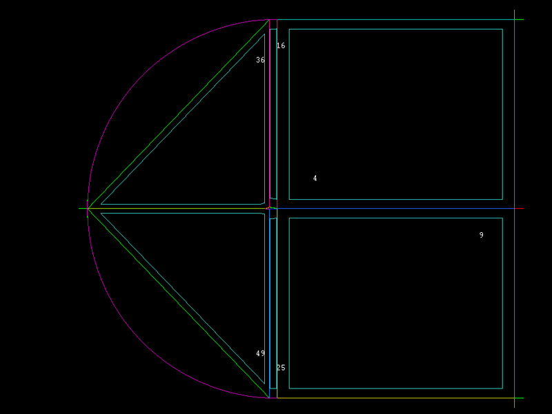 so, from AOA -4 to -1, I put wall free. ( I think opening should work ok) in AOA=0 I used symmetry. and from AOA 2 to 12 I used wall free again ( I think opening should work ok). You should do some analysis changing those BC and pick the BC that give you best results.(validate your model from a real experiments, NACA report helped in my case). 2. The results of the Y+, you can look it the results from CFX Post; is a variable like others. I suggest to look in ansys help. They explain the concept, and is a very important parameter. Depending in the Turbulence model, you will need a range of Y+. In my model, initially I worked with SST (works good from AOA -2 to 10). When the airfoil aproximates to AOA=12 or the stall state, the Turbulence model doesnt work very good.The Y+<2 to SST. (if I dont forget) For my model, I got a little better aproximation in the variables (Cd Cl) with GAMMA THETA - Langtry menter Turbulence Model , but I got some convergence problems. Y+<2. this was my mesh (made in ICEM): 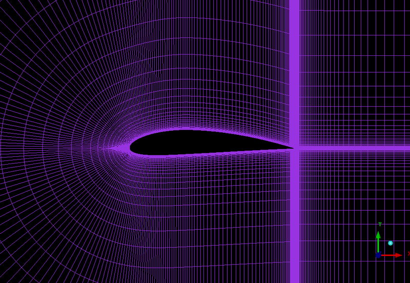 I hope it helps. Cheers, Santiago O. |
|
|
|
||
|
June 16, 2007, 07:28
|
|
#6 |
|
Guest
Posts: n/a
|
Hurry
|
|
|
|
||
|
June 17, 2007, 17:59
|
|
#7 |
|
Guest
Posts: n/a
|
hi Santiago would you please give me an idea about the procedure you followed to create your blocks, i tried to understand it my self but i couldnot
thanks |
|
|
|
||
|
June 19, 2007, 09:11
|
|
#8 |
|
Guest
Posts: n/a
|
Hello Hamman. Sincerly I dont remeber exactly the procedure. But, the way I create the blocks, its kind of rustic and slowly, but far now, its my best way to make blocks. So, each block its defined by 4 points (the 4 corners of any block). So create in ICEM the 4 points of each corner of each block, in the GEOMETRY part. (in my case I created 2 points in the airfoil curve, and 2 in the domain curve, as you can see in the pic). Do that for each block (You will need a little of imagination; I suggest to draw the blocks in a piece of paper and then creat the points). Then begin the process of creating all the blocks of the domain, using the Splitting tool or what ever you want. Then ASSOCIATE each corner or vertice of a block, with each point you have created. I hope you understand.
Its kind of slowly, rustic, etc, etc; but for me, have worked very good. Feel free to ask if you dont understand. Cheers, santiago. |
|
|
|
||
|
June 19, 2007, 09:13
|
|
#9 |
|
Guest
Posts: n/a
|
I made an acclaration: "So create in ICEM the 4 points of each corner of each block, in the GEOMETRY part. (in my case I created 2 points in the airfoil curve, and 2 in the domain curve, as you can see in the pic)" -----> thats for block 36
|
|
|
|
||
|
June 21, 2007, 18:48
|
|
#10 |
|
Guest
Posts: n/a
|
hi Santiago
i think i managed make the blocks as yours but thr problem now is with the mesh setup can you help me with mesh setup please? thanks |
|
|
|
||
|
June 22, 2007, 13:18
|
|
#11 |
|
Guest
Posts: n/a
|
Sure, what is your problem???? email me if you want. Santiago.
|
|
|
|
||
 |
|
|
 Similar Threads
|
||||
| Thread | Thread Starter | Forum | Replies | Last Post |
| Multi-element airfoil analysis | CFD Rookie | Main CFD Forum | 12 | November 17, 2016 06:07 |
| Steady level flight airfoil analysis using ANSYS CFX v12 | flutter | CFX | 21 | March 29, 2016 03:51 |
| Airfoil Mesh for DES Analysis - y+ Value | asd | Main CFD Forum | 1 | May 3, 2007 10:13 |
| y+ for Airfoil Analysis | asd | Main CFD Forum | 3 | April 18, 2007 10:54 |
| quasi steady analysis of 2d airfoil (pitching) | Alex | FLUENT | 1 | February 10, 2006 02:54 |
 Linear Mode


