|
|
|
[Sponsors] | ||||
 February 13, 2023, 04:53
|
|
#1 |
|
New Member
Join Date: Feb 2023
Posts: 6
Rep Power: 3  |
Dear Forum Members,
I'm moddeling a radial compressor with an vaned diffusor and volute in CFX steady state. For geometry generation i use blade gen and turbo grid for meshing. The volute is a iges file imported in geometry and meshed with an unstructured mesh of tetrahedrons. My system has the following BC conditions: - stationary temperature and total pressure at rotor inlet - massflow rate at outlet (volute outlet) - stage mixing at rotor / stator Interface (with frozen rotor initial solution) - frozen rotor at diffusor / volute - wall (no slip) at walls - periodic BC for the periodic walls (obvious) 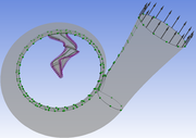  For a low nodecount mesh (300K - 500 K nodes for rotor / diffusor respective) i can obtain a solution without oscillations in the residuals. The system converges for low massflow rates as well as for high ones (near diffusor stall) 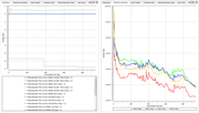  While doing the mesh studys the system is not converging as before. The finer mesh has rotor = 1,65*10^6, stator = 3,16*10^6, volute = 1,84*10^6 nodes . I have a y+ of ~ 30 for rotor and vaned diffusor. The boundary layer mesh was generated according to Re-No and desired y+. I was able to get a converged solution for the design point of the compressor by using a frozen rotor BC between Rotor / stator first and then changing the BC to stage mixing. After that i calculate the speed line at 100% by changing the massflow rate to higher and lower values and using the converged solution from the design point as initial condition. This works well for cases with lower massflow rate than the design point and slightly higher values. For higher massflow rates the solution tends to oscillate more and more with increasing massflow rate. I also notice that the boundary massflow rate at the inlet is oscillating. 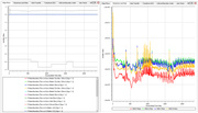  I have also tried changing the timesteps from the turbo systems ramping function to physical timescale = automatic, with no success. I have also tried changing the timesteps from the turbo systems ramping function to physical timescale = automatic, with no success. Could it be possible that the rotor / stator interaction causes the oscillations with a finer mesh becuause the wakes of the rotor are predicted more accuratly? Does anyone knows what to do in such a situation? Thanks in advance for the answers. |
|

|

|
|
|
February 13, 2023, 11:09
|
|
#2 |
|
Senior Member
Daniel
Join Date: Feb 2017
Location: Germany
Posts: 147
Rep Power: 9 |
Did you consider to look at your MAX Residual nodes ?
This will clear things up, where your maximum residuals appear - probably at the volute tongue or the impeller trailing edge as you already guessed. |
|
|
|
|
|
|
February 13, 2023, 16:42
|
|
#3 |
|
Super Moderator
Glenn Horrocks
Join Date: Mar 2009
Location: Sydney, Australia
Posts: 17,703
Rep Power: 143 |
Have a look at the FAQ on this: https://www.cfd-online.com/Wiki/Ansy...gence_criteria
It is normal for a coarse mesh simulation to converge well but as you refine the mesh convergence gets more difficult. In steady state runs this is caused by the mesh now having less dissipation and therefore resolving smaller flow structures, and those small flow structures are transient and so limit the amount of steady state convergence which can be obtained. The FAQ discusses what to do in this situation.
__________________
Note: I do not answer CFD questions by PM. CFD questions should be posted on the forum. |
|
|
|
|
|
|
February 13, 2023, 16:48
|
|
#4 |
|
Senior Member
Gert-Jan
Join Date: Oct 2012
Location: Europe
Posts: 1,827
Rep Power: 27 |
- I think you should solve this full 3D, transient with a timestep equal to approx 2 degree rotation.
- A finer mesh is always more difficult to converge since more detailed flow phenomena appear with shorter time scales, meaning timesteps should decrease to solve them probably. There is no work around. Alternatively, use a coarse mesh. Then convergence is easier. |
|
|
|
|
|
|
February 13, 2023, 18:24
|
|
#5 |
|
Senior Member
Join Date: Jun 2009
Posts: 1,804
Rep Power: 32 |
You are modeling a compressor, so careful here on how you increase or decrease your mass flow rate. You have not mentioned how far from the design point you are, nor how close you are getting to the surge/stall point or the choke point.
You do not have free range to change the mass flow as a boundary condition. You are limited by physics: there is a maximum mass flow you can push through the machine (choke point), and there is a minimum mass flow the machine can sustain. How close are you from those two limits? For some machines the range is narrow, and for other is wide. There is no universal rule unless you know the specifics and the application for that compressor.
__________________
Note: I do not answer CFD questions by PM. CFD questions should be posted on the forum. |
|
|
|
|
|
|
February 14, 2023, 01:40
|
|
#6 | |
|
New Member
Join Date: Feb 2023
Posts: 6
Rep Power: 3 |
Quote:
Shure. The compressor i am moddeling here was built before and i know the measured speedline, so i know where the limits of the compressor are. For a coarser mesh the calculated speedline is already quite close to the measured one. To study my cfd i wanted to solve the problem with i finer mesh to see how the influence on the solution is (as you do for mechanical FEM.... now i see for CFD it's more difficult  ) )
|
||
|
|
|
||
|
February 14, 2023, 01:45
|
|
#7 | |
|
New Member
Join Date: Feb 2023
Posts: 6
Rep Power: 3 |
Quote:
This could be interesting! Can you tell me where i have to look for this information. |
||
|
|
|
||
|
February 14, 2023, 07:49
|
|
#8 | |
|
Senior Member
Daniel
Join Date: Feb 2017
Location: Germany
Posts: 147
Rep Power: 9 |
Quote:
The Node numbers as well as the domain, where the MAX residuals appeared, are mentioned. In CFD Post you can create a Point and choose a Node Number as your location on the mesh. |
||
|
|
|
||
 |
|
|
 Similar Threads
|
||||
| Thread | Thread Starter | Forum | Replies | Last Post |
| Set local radial axis for radial velocity with UDF | vincenzolights | FLUENT | 1 | April 8, 2022 03:13 |
| Formulation of the Radial Acutation Disk Source | antar | OpenFOAM Programming & Development | 3 | November 3, 2019 02:20 |
| Mean/RMSE Radial Velocity Profile: Unsteady Simulation | delliganesh07 | FLUENT | 0 | August 31, 2019 11:05 |
| What is "Lock-In" in oscillating cylinder problem? | 9mile | Main CFD Forum | 0 | June 3, 2015 09:57 |
| Radial Load calculation | pump_passion | CFX | 3 | March 31, 2010 17:51 |
 2Likes

 Linear Mode


