|
|
|
[Sponsors] | ||||
 April 5, 2020, 00:37
|
|
#1 |
|
Member
Join Date: Jan 2020
Posts: 31
Rep Power: 6  |
hello every one ...
I need someone to write this UDF for me! I tried but I couldn't! can you help me? more than 6 months I am working on it! the formulas are like the pictures and the description of the UDF Is placed 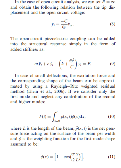 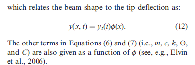  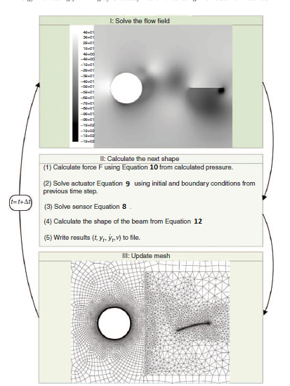
|
|

|

|
|
|
April 6, 2020, 08:25
|
|
#2 |
|
Senior Member

|
Could you attach your mesh file here?
__________________
Regards, Vinerm PM to be used if and only if you do not want something to be shared publicly. PM is considered to be of the least priority. |
|
|
|
|
|
|
April 6, 2020, 08:51
|
|
#3 | |
|
Member
Join Date: Jan 2020
Posts: 31
Rep Power: 6 |
Quote:
here is my mesh: https://gofile.io/?c=SiE9S8 also, L=0.03 in the UDF thanks |
||
|
|
|
||
|
April 6, 2020, 08:53
|
|
#4 |
|
Senior Member
|
I will look into it.
__________________
Regards, Vinerm PM to be used if and only if you do not want something to be shared publicly. PM is considered to be of the least priority. |
|
|
|
|
|
|
April 8, 2020, 07:29
|
|
#5 |
|
Senior Member
|
I tried by giving a displacement that is defined by the equation given but in a modified form. Modification is required because you have it other way around, i.e., you need to have 0 displacement at x = L. The original equation will give you maximum displacement at x = L. So, that's one thing you need to change.
 = 1-cos\left(\frac{\pi(L-x)}{2L}\right)") Secondly, this equation appears to be assuming linearity. Because this becomes invalid with any finite deformation; the length of the beam shortens. Therefore, you also need to include the update of x position of node and not just y. You have to derive the equation for x yourself, but it would be pretty straightforward assuming length of beam is constant. Secondly, refine the mesh around the beam, across its thickness, to get better resolution. And now on to your main problem that you mentioned, i.e., beam kind of getting compressed or expanded instead of pure motion. The reason for that is that you are using y-coordinate of each node for movement of each node. That is causing the trouble.  is always positive. So, the direction of motion depends upon the value of y being positive or negative. Those with negative values try to move in a direction opposite to those with positive values. So, either the beam expands or contracts. You have to ensure that you use only one value for each x-coordinate to determine the movement. You can choose either upper surface or lower surface. is always positive. So, the direction of motion depends upon the value of y being positive or negative. Those with negative values try to move in a direction opposite to those with positive values. So, either the beam expands or contracts. You have to ensure that you use only one value for each x-coordinate to determine the movement. You can choose either upper surface or lower surface.
__________________
Regards, Vinerm PM to be used if and only if you do not want something to be shared publicly. PM is considered to be of the least priority. |
|
|
|
|
|
|
May 1, 2020, 04:56
|
|
#6 | |
|
Member
Join Date: Jan 2020
Posts: 31
Rep Power: 6 |
Quote:
I think my UDF is at the end of its construction with your help. I think this is my last problem: "with the following formula: NODE_Y = NODE_Y +F_UDMI(f, tf, 2)" I want the second NODE_Y always be the first time step NODE_Y. how can I do it? after the end of each loop I want NODE_Y to change to the NODE_Y at the first time step for the next loop to addition with F_UDMI(f, tf, 2) and create the new NODE_Y and again and again. Thanks a lot My code: begin_f_loop(f,tf) { f_node_loop(f,tf,n) { v = F_NODE(f,tf,n); if ( NODE_POS_NEED_UPDATE (v)) { NODE_POS_UPDATED(v); yy = 1-cos((PI/2)*(NODE_X(v)/L)); F_UDMI(f, tf, 2) = yy*yold; F_UDMI(f, tf, 3) = NODE_Y(v)/(NODE_X(v)+0.00001); tteta1 = F_UDMI(f, tf, 3) * (PI/180); tteta2 = asin(tteta1) + 2*PI; F_UDMI(f, tf, 4) = cos(tteta2); F_UDMI(f, tf, 5) = F_UDMI(f, tf, 4) * NODE_X(v); NODE_X(v) = F_UDMI(f, tf, 5); NODE_Y(v) = NODE_Y(v) + F_UDMI(f, tf, 2); } } } end_f_loop(f,tf); |
||
|
|
|
||
|
May 1, 2020, 15:12
|
|
#7 |
|
Senior Member
|
It would be impossible if there is remeshing taking place since the nodes are reset. Otherwise, you can create a Node UDM and the store the initial node locations. Then, you can use values from that UDM. Node UDM is separate from Cell (and Face) UDM.
__________________
Regards, Vinerm PM to be used if and only if you do not want something to be shared publicly. PM is considered to be of the least priority. |
|
|
|
|
|
|
May 11, 2020, 12:51
|
|
#8 | |
|
Member
Join Date: Jan 2020
Posts: 31
Rep Power: 6 |
Quote:
|
||
|
|
|
||
|
May 11, 2020, 13:23
|
|
#9 |
|
Senior Member
|
Similar to cell based UDMs, there are node UDMs. You can execute a function to go over all the nodes in the domain and save the position coordinates in node UDM. You do not need to use a dynamic mesh UDF. Any general purpose UDF will work, such as, DEFINE_ON_DEMAND or DEFINE_EXECUTE_ON_LOADING.
__________________
Regards, Vinerm PM to be used if and only if you do not want something to be shared publicly. PM is considered to be of the least priority. |
|
|
|
|
|
|
May 12, 2020, 00:39
|
|
#10 | |
|
Member
Join Date: Jan 2020
Posts: 31
Rep Power: 6 |
Quote:
am I right? |
||
|
|
|
||
|
May 12, 2020, 07:05
|
|
#11 |
|
Senior Member
|
You need to use a macro that does not require you to run the simulation. Dynamic mesh macros are executed only when you run the case. If you run the case, the nodes might move in the very first time-step.
You don't need to write a long function. You already have dynamic mesh UDF. Just call it will proper arguments within DEFINE_ON_DEMAND. If the name of the dynamic mesh UDF is moveNode or cantilever, just call it by its name within DEFINE_ON_DEMAND and rest of the arguments of the dynamic mesh UDF must be given as input arguments to this function call. If you find it difficult, then just make a copy of your dynamic mesh UDF wherein you only copy node location to node UDMs. Run it but only for one time-step with a very very small value for time-step so that nodes do not move.
__________________
Regards, Vinerm PM to be used if and only if you do not want something to be shared publicly. PM is considered to be of the least priority. |
|
|
|
|
|
 |
| Tags |
| #udf#blade#displacement |
|
|
 Similar Threads
|
||||
| Thread | Thread Starter | Forum | Replies | Last Post |
| UDF for vapor pressure | anuarun | Fluent UDF and Scheme Programming | 12 | December 24, 2021 10:12 |
| Replicating Scalable Wall Function with a UDF | yousefaz | FLUENT | 0 | August 4, 2017 02:30 |
| UDF in Fluent | Andrew | Fluent UDF and Scheme Programming | 5 | March 7, 2016 03:38 |
| Displacement of particles with an udf | Michael Heim | FLUENT | 0 | July 6, 2004 14:08 |
| UDF, UDF, UDF, UDF | Luc SEMINEL | Main CFD Forum | 0 | November 25, 2002 04:01 |
 2Likes
 Linear Mode


