|
|
|
[Sponsors] | ||||
 August 11, 2016, 05:34
|
|
#1 |
|
Senior Member
Join Date: Nov 2015
Posts: 135
Rep Power: 10  |
So I have a pinhole of 1mm diameter and I want to model the flow through that nozzle. The pressure on the side infront of the nozzle is 250mbar but that doesnt really matter for my case, since I presume its too difficult to model both parts simultaneously. Therefore (since I do know the exact flow through that nozzle anyway) I just model the flowregion and consider the orifice as a mass-flow-inlet. The flow-region behind the nozzle is at 275 Pascal. The mass flow through that nozzle is 0.04g/s.
The geometry is cylindrically symmetric and for the sake of numerical stability I meshed the innermost part of the cylinder very fine in order to capture as many features as possible. The entire geometry is 4cm diamater of the tube and 25cm long seen here. The mesh in the small inner cylinder which is affected by the beam behind the nozzle most is roughly 0.1-0.5mm and the minimum length is set to 0.05-0.1mm (the region again is divided into two parts (one directly behind the nozzle for the frist 5mm and the second from then on) Now: I've tried different setups running but it seems to be pretty dependent on the Method I'm using. So far I presume the SST-transition model is doing the best job. Has anyone experience which model is the best for a critical orifice with strong gradients in bascially everything? I feel like k-omega-SST doesnt really capture it though I dont know why... what about reynold-stress model or k-epsilon..For this specific lineup to capture the supersonic beam (it tells me velocities up to 750m/s right behind the nozzle) and it's shock fronts while separating this beam to the rest what should be the model of choice? As a side note: The solver tells me every iteration, that the temperature is limited to 1 in 2 cells in some domain. I'm using Soave-Redlich-kwong real gas model. |
|

|

|
|
|
August 12, 2016, 11:40
|
|
#2 |
|
Senior Member
Join Date: Nov 2015
Posts: 135
Rep Power: 10 |
Noone here who might have some experience in modelling a critical nozzle with supersonic expansion??
What method is advisable and maybe some tweaks? |
|
|
|
|
|
|
August 12, 2016, 21:07
|
|
#3 |
|
Senior Member
Lucky
Join Date: Apr 2011
Location: Orlando, FL USA
Posts: 5,672
Rep Power: 65 |
Turbulence doesn't play much of a role in this type of flow. It's mostly inviscid. I think you can use just about any turbulence model unless you really care about having super high accuracy. But if you want that super high accuracy then it is of utmost importance to also model the flow coming into your nozzle (which is much more important than any turbulence).
Figure out where the cells are where the temperature is being limited and try to figure out why it's being limited there. Is it the minimum temperature limit (most likely) or the maximum temperature limit? Understanding the equation of state is really important for debugging this type of problem. Is it at the exit boundary or is it immediately after the orifice? Maybe it's a meshing problem? |
|
|
|
|
|
|
August 13, 2016, 07:25
|
|
#4 |
|
Senior Member
Join Date: Nov 2015
Posts: 135
Rep Power: 10 |
Thx for ur answer:
Just for clarification I added some scetch about how the nozzle is shaped and the flow will go (according to my imagination of it)  So directly behind the nozzle the expansion will be supersonic with all the features of air cooling down for example until it hits some shockfront and the flow widens up to be sort of laminar in the rest of the tube. It says: temperature limited to 1.000000e+00 in 2 cells on zone 11 in domain 1 Is that possible that the calculation tells u that or is it surely a representation of a "bad" mesh? I mean since I do expect significant downcooling of the air I'm not surprised it gets very cold...The question is if its not even possible to resolve to requried scales there and then any further effort might be wrongly invested... I already have mesh with over 1million cells where most of the are located at the critical regions... Btw: How do I find out if it says zone 11 in domain 1 where precisely that is? I guess it its directly behind the nozzle, which is reasonable , but is there a way to visualize this zone 11 in domain 1 ??? Also: Why do u say turbulence doesnt play a role? Isn't the supersonic expansion already highly turbulent by itsself? In particular the boundary areas to the beam where fast air meets slow air at the sides and high shear forces are to be expected?!? edit: within the region I'm going to show is also (actually at the very tip) region where the 1K lower limit is applied: What I noticed is weird is the sum of static + dynamic pressure which would I suppose is total pressure, right? 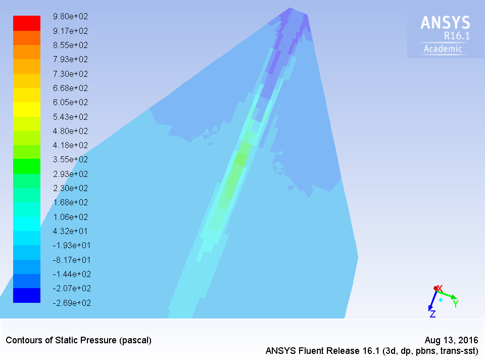 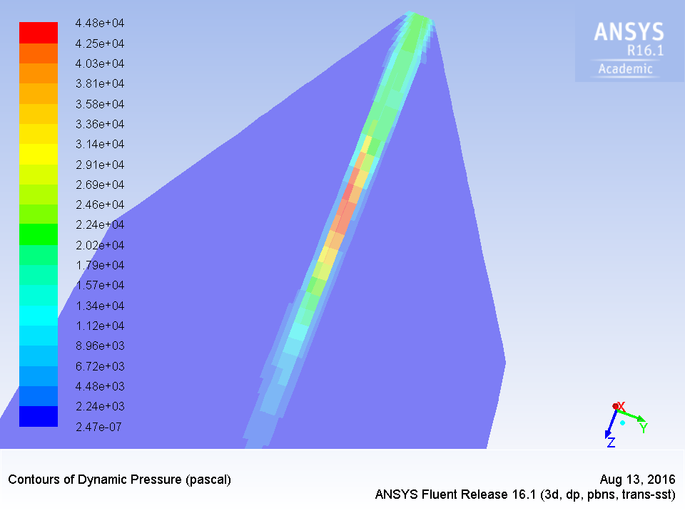 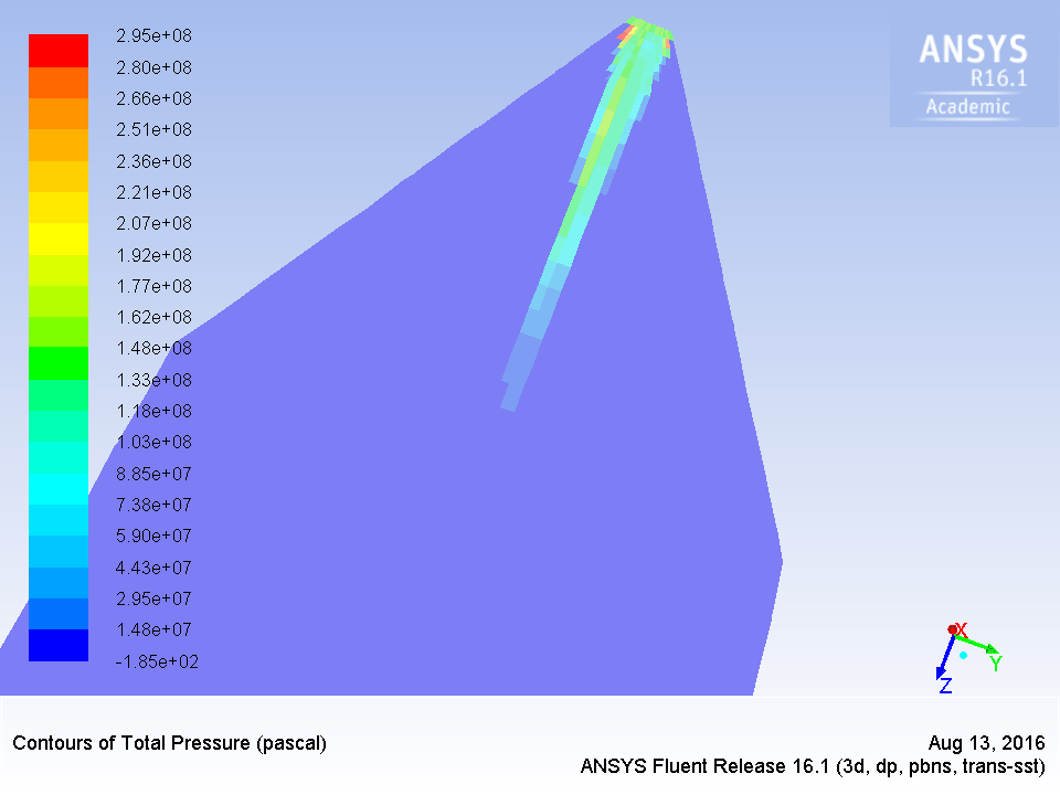
Last edited by Diger; August 13, 2016 at 08:44. |
|
|
|
|
|
 |
|
|
 Similar Threads
|
||||
| Thread | Thread Starter | Forum | Replies | Last Post |
| Two-phase critical flow and shock modelling of nozzle | Jeggi | STAR-CCM+ | 0 | December 4, 2014 09:12 |
| Modelling a restriction orifice | ADGlassby | CFD Freelancers | 1 | January 17, 2014 15:00 |
| Turbulence modelling validation : Orifice flow | Joe | Main CFD Forum | 2 | July 26, 2006 16:41 |
| Modelling gas flow through a small orifice | dannyboy | OpenFOAM Running, Solving & CFD | 1 | June 23, 2005 13:18 |
| critical orifice | hedonists | FLUENT | 0 | March 16, 2004 10:47 |
 Linear Mode


