|
|
|
[Sponsors] | ||||
 September 10, 2009, 16:36
|
|
#1 |
|
New Member
Mark Harvey
Join Date: Sep 2009
Posts: 5
Rep Power: 16  |
Hello, I am working on a project with a local company doing airflow testing over roof mounted solar panels. The company has given me 3d models of a solar panels and roof racks in solidoworks, and I have converted to to parasolid format and imported into Gambit. The geometry is very complex and I do not seem to be having any luck meshing in Gambit. Any advice?
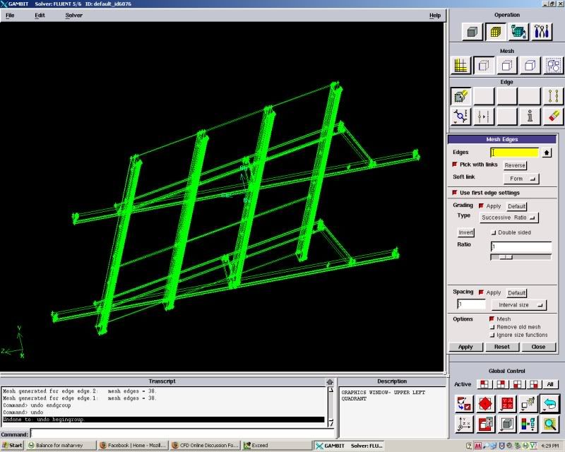 I can can email somebody the file so they can better help. |
|

|

|
|
|
September 10, 2009, 17:22
|
|
#2 |
|
Senior Member
Ahmed
Join Date: Mar 2009
Location: NY
Posts: 251
Rep Power: 18 |
1- you need to place that structure on a standard roof, that is just a surface that will represent the lower boundary of your flow domain
2- define each part as a volume . 3- define your flow domain (you have the lower boundary defined in step 1) then draw a big mushroom like shape. 4- subtract 2 from 3 That will leave your flow domain Good Luck |
|
|
|
|
|
|
September 10, 2009, 18:36
|
|
#3 |
|
New Member
Mark Harvey
Join Date: Sep 2009
Posts: 5
Rep Power: 16 |
Thank you for the response, but I am just looking to mesh the structure right now. Any tips on how to do this?
|
|
|
|
|
|
|
September 10, 2009, 21:37
|
|
#4 | |
|
Senior Member
Ahmed
Join Date: Mar 2009
Location: NY
Posts: 251
Rep Power: 18 |
Quote:
Are you planning for a CFD or structural/thermal conduction analysis? any way, in Gambit, and for a 3D analysis, define the parts you want to mesh as volumes then mesh them (just step 2 mentioned before). You can use bolean operations to combine every thing into one volume, if that suits your analysis. Look, on this particular forum the members discuss problems related to fluid/thermal problems, the more details you give, the more appropriate answers will be received. Good luck |
||
|
|
|
||
|
September 11, 2009, 09:34
|
|
#5 |
|
New Member
Kishore Kumar C
Join Date: Sep 2009
Location: Bangalore
Posts: 12
Rep Power: 16 |
Hi,
If you can define your flow domain clearly it would be easier to help you out. I dont see any surfaces or boundaries over which there is going to be airflow. I suggest you to create an unstructured grid for this kind of geometry with local refinement. I suggest you to use ICEM CFD in case you have it, It would make your life easier. |
|
|
|
|
|
|
September 11, 2009, 17:06
|
|
#6 | |
|
New Member
Mike Jenkins
Join Date: Apr 2009
Location: Kansas City
Posts: 9
Rep Power: 17 |
Get the part into ProE or some decent CAD program with a plug in for CFX.
Create a dummy air part which covers the whole structure. Subtract the structure from the air part. Open the air part and use the plug in to transfer the part into DesignModeler. Create a mesh from the DesignModeler geometry using the Meshing applet for CFX. If the meshing applet has some error to mesh the complicated geometry, try to reduce rounds and other trivial features on the Solidworks assy. Maybe you can change the beam cross sections to square? If that doesn't work, try changing the face space and line space of your mesh down to .01 inch, .009 inch, .005 inch or however much your processor can take!!! Quote:
|
||
|
|
|
||
 |
|
|
 Similar Threads
|
||||
| Thread | Thread Starter | Forum | Replies | Last Post |
| Meshing Complicated Geometry(pic) | maharvey | FLUENT | 2 | September 14, 2009 01:15 |
| Please help in meshing this complicated geometry | eers | Main CFD Forum | 7 | July 8, 2009 20:42 |
| Meshing of very complicated part | Sanjay Jain | FLUENT | 9 | April 7, 2009 00:21 |
| Singularity of grid?Volume meshing vs face meshing | Ken | Main CFD Forum | 0 | September 4, 2003 11:09 |
| Volume Meshing & Face Meshing? singularity of grid | ken | FLUENT | 0 | September 4, 2003 11:08 |

 Linear Mode


