|
|
|
[Sponsors] | ||||
 October 15, 2019, 03:28
|
|
#1 |
|
New Member
Matte Wang
Join Date: Sep 2018
Posts: 13
Rep Power: 7  |
Dear Niels
Thank you for your eminent toolbox, I have learned a lot from it. Recently, I want to make a extension for its wave models, i.e. , Internal Solitary Wave Models. Unfortunately, I encounter a problem when I set up my case. The strategy of my wave model is: 0. Create a new class. 1. Using the solution of KDV equation, acquire eta, and then add this in member function. 2. Using the solution of KDV equation, acquire Uupper and Ulower, add this in member function. 3. Modify waveVelocityFvVectorField.C The function will divide faces into 3 types, negative, position and both according to member function eta. The negative means that this face is located on lower layer since I could give this boundary a velocity according to KDV solution for lower layer. This step is fully the same to surface water. The positive means that this face is located on upper layer since I could give this boundary a velocity according to KDV solution for upper layer. This step should make a modification in waveVelocityFvVectorField.C to replace the wind velocity in this class. The faces are both positive and negative should make a interpolation: U=negMag/MagSf ×lowerU(negCenter)+posMag/MagSf*upperU(posCenter) 4. Modify setWaveField.C Similar to step 3. 5.Modify transportProperties, replace air with low density water. 6. None relaxationZone is used. 7. None pExcess is used. And then, after setWaveField, I got this image which is quite similar to the result in the paper 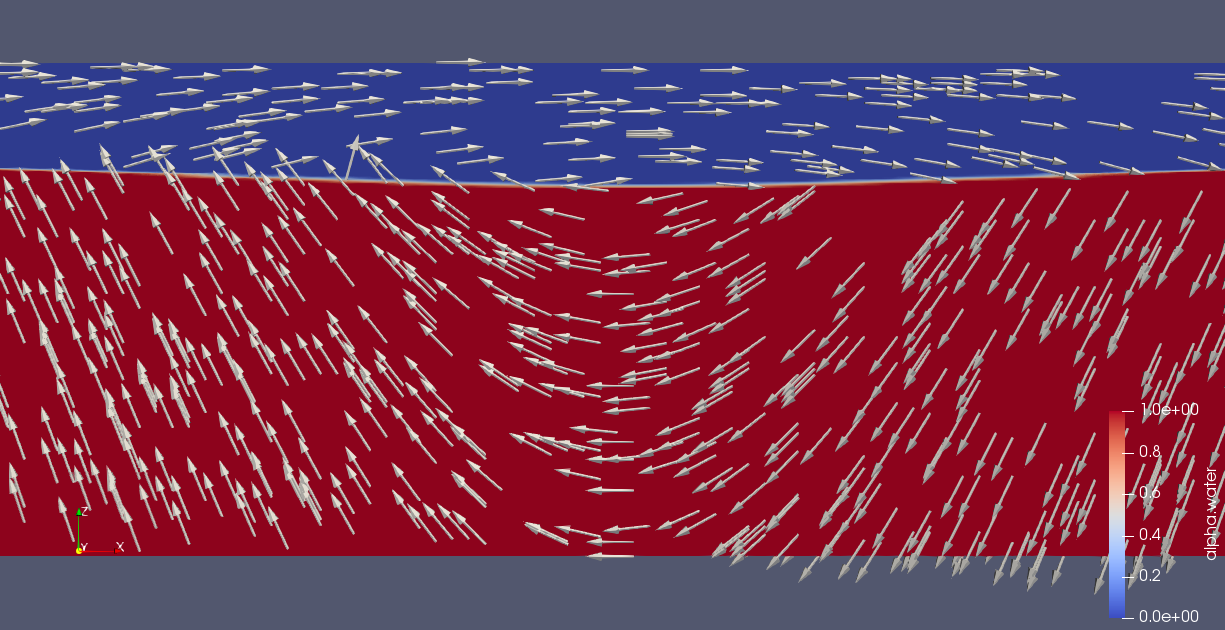 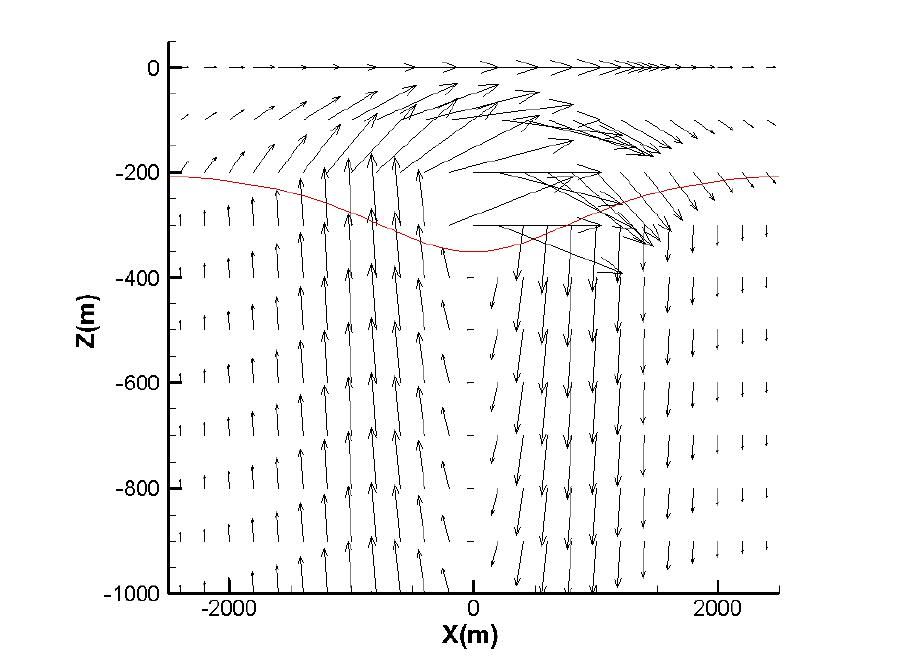 Unfortunately, things go wrong after I starting my simulation. The lower water gradually rise up on the left side and the interface collapse in 3 seconds. At the same time, there are a lot of mixture distributing in upper layer. Anyway, could you give me some advice about that? Thank you very much. Last edited by Aunura; October 15, 2019 at 06:01. Reason: adding more information |
|

|

|
|
|
October 15, 2019, 05:59
|
|
#2 |
|
New Member
Matte Wang
Join Date: Sep 2018
Posts: 13
Rep Power: 7 |
$--------------------------------------------------------------------------------------------------------------------------------------------------------------------------------
Some calculated results: Crest locates on the left side of calculated zone t=0, initial Fields:   t=0.005 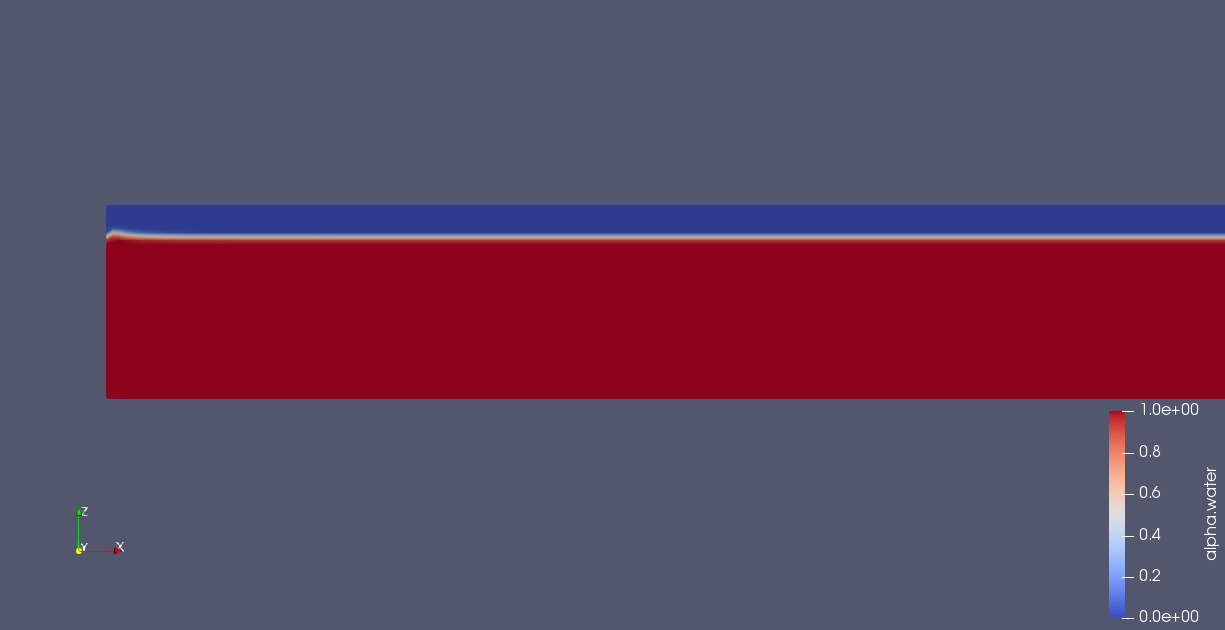 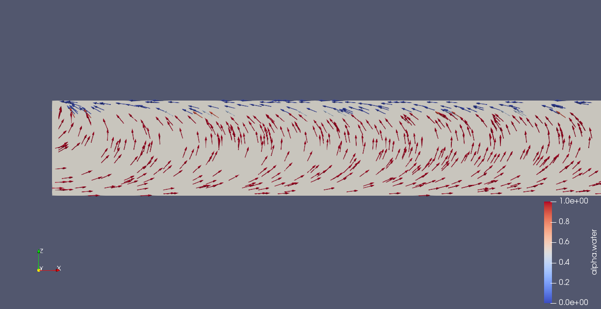 Crest locates on the x=0 t=0, initial Fields: 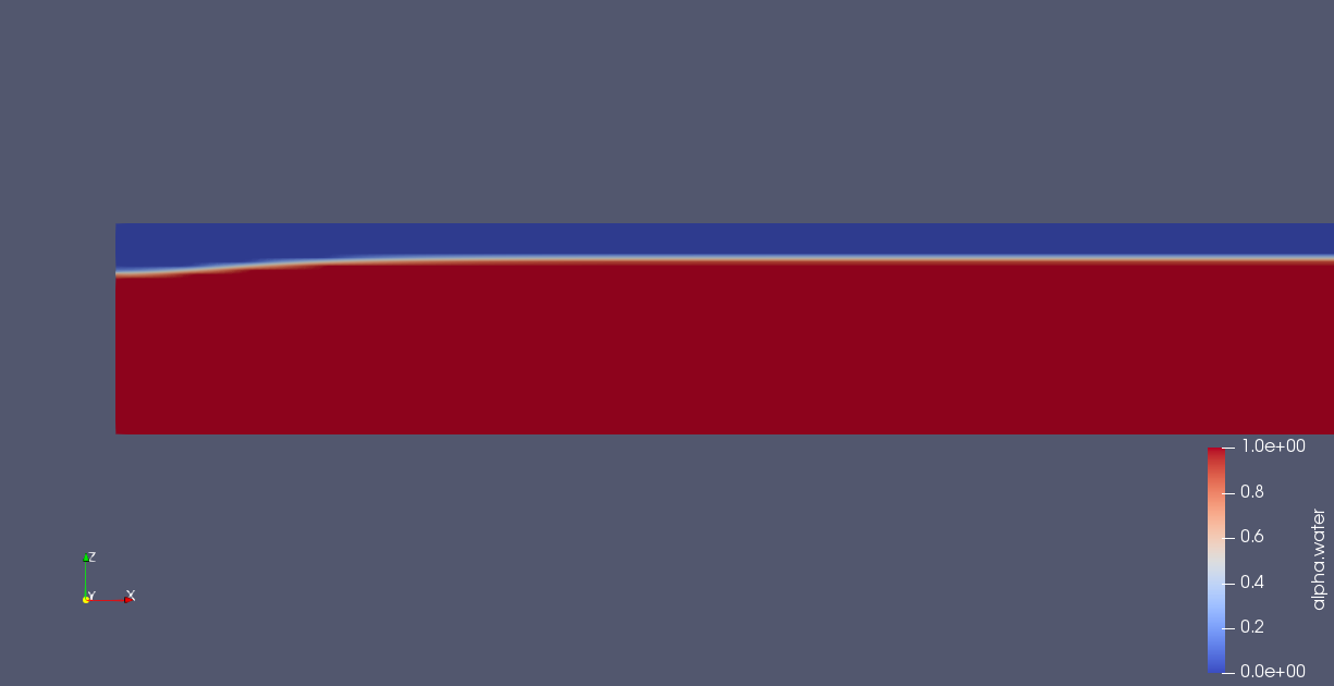 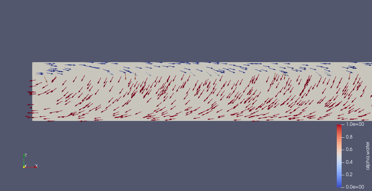 t=0.005 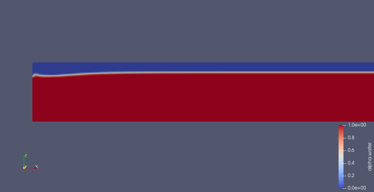 
|
|
|
|
|
|
|
October 15, 2019, 06:00
|
|
#3 |
|
New Member
Matte Wang
Join Date: Sep 2018
Posts: 13
Rep Power: 7 |
Crest locates on the x=2.5
t=0, initial Fields: 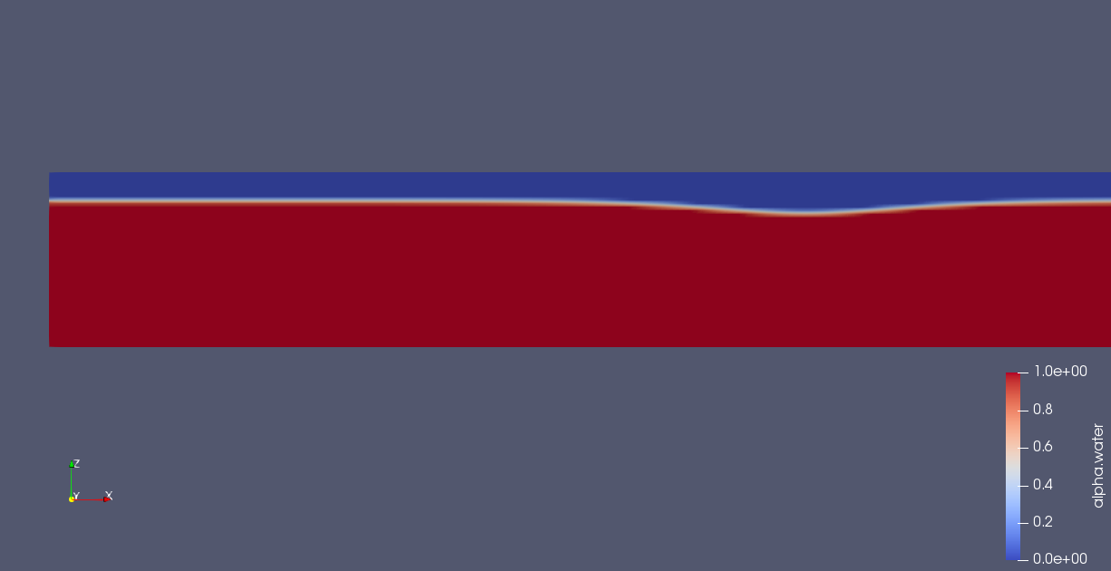 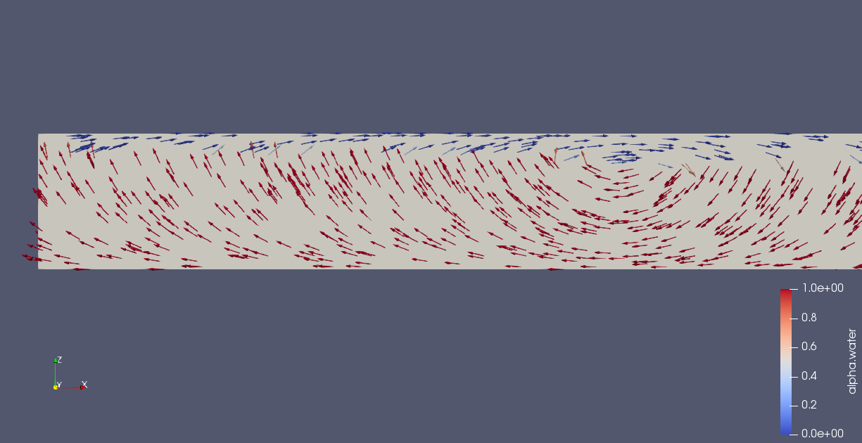 t=0.005 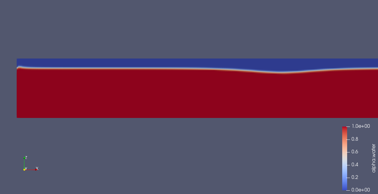 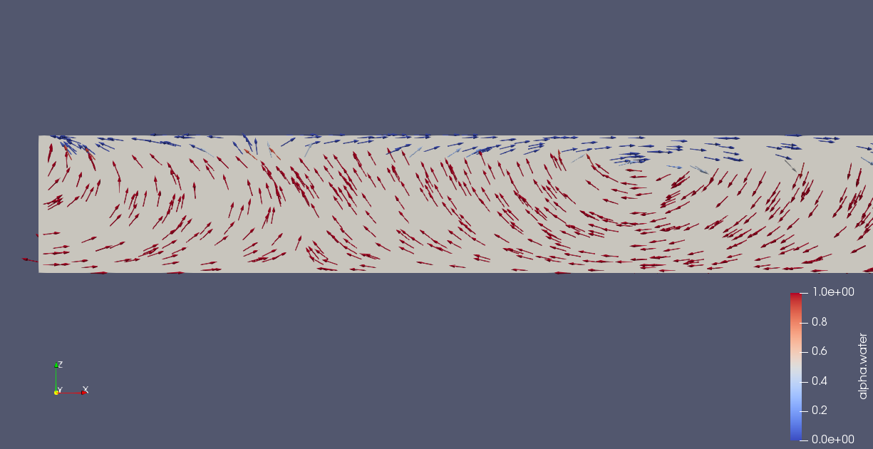 Crest locates on the x=5 t=0, initial Fields: 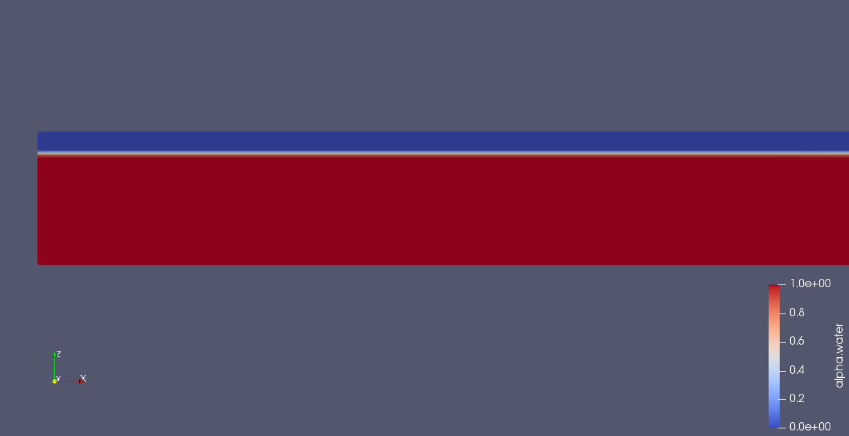 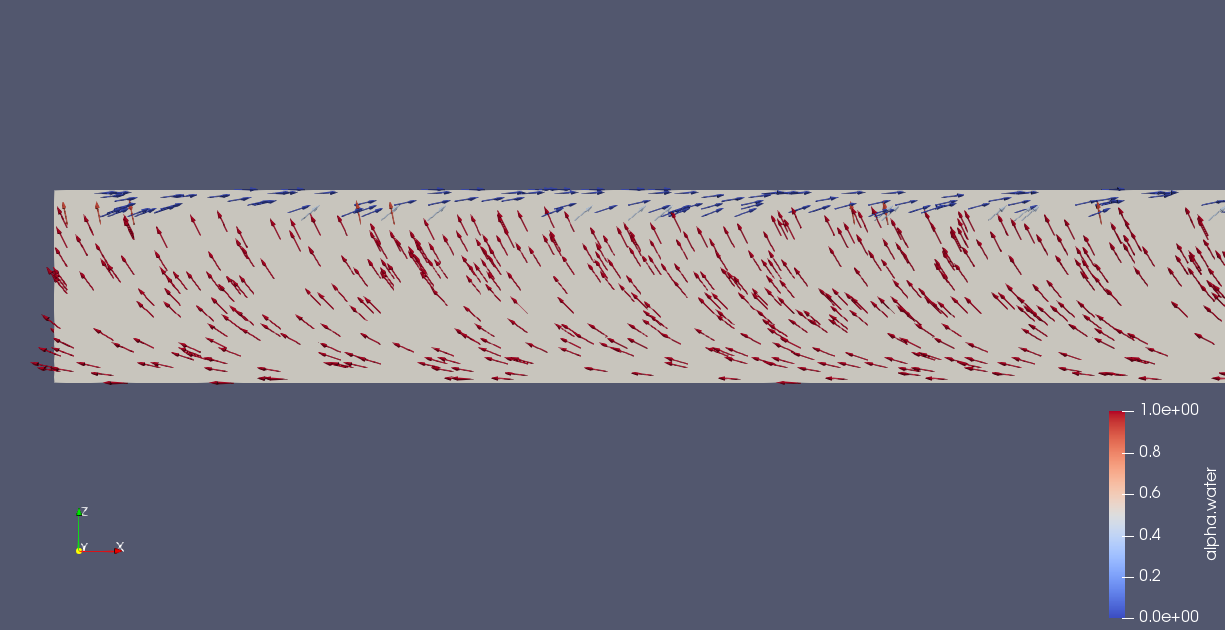 t=0.005 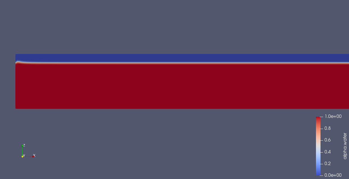 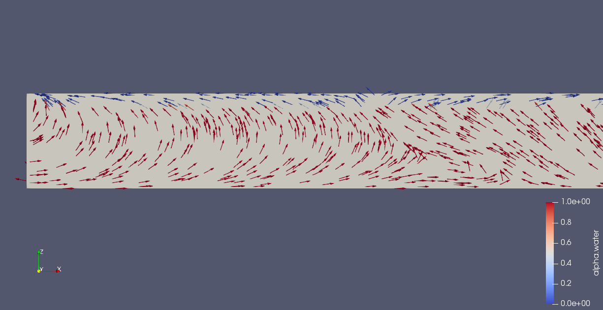 It seems that the initial field, which is set according to analytical solution or potential flow theory, is entirely different from the solution calculated by N-S equation or interFoam. Therefore, the fields cannot maintain its value. However, one of my friend get good results according to the same equation via ANSYS FLUENT. I don't know the reason why my case doesn't work. Does anyone have some ideas? |
|
|
|
|
|
 |
|
|
 Similar Threads
|
||||
| Thread | Thread Starter | Forum | Replies | Last Post |
| simple problem with internal faces Boundary condition | mrshb4 | OpenFOAM Pre-Processing | 25 | April 21, 2022 01:11 |
| Mesh& steptime independant: conduction-convection problem | Fati1 | Main CFD Forum | 1 | October 28, 2018 13:52 |
| Problem with: 'Divergence detected in AMG for Coupled: protective actions enabled!' | dengdeng | FLUENT | 1 | September 22, 2018 10:27 |
| [Salome] ideasUnvToFoam problem with internal groups | s.marcocalero | OpenFOAM Meshing & Mesh Conversion | 0 | May 31, 2013 11:48 |
| Internal Heat generation problem | ldcairan | ANSYS | 0 | November 19, 2010 13:21 |
 Linear Mode


