|
|
|
[Sponsors] | ||||
 April 6, 2017, 10:05
|
|
#1 |
|
Member
Teresa
Join Date: Nov 2015
Location: germany
Posts: 63
Rep Power: 10  |
Hi all,
I am currently working with this example: https://openfoamwiki.net/index.php/2...ial_using_GMSH A axisymmetric stenosis is not far from what I want to calculate in the end so it is a testing/learning case and later on I will need to go to more complex geometry (but still 2D). But first I have to learn how to use gmsh and rhoPimpleFoam. However I can't make the transition between gmsh and openFoam work. When I try to use gmsh to Foam there is this undefined faces error which I read can possibly be ignored. But there is a second problem without a failure warning: The resulting Mesh is 3D. So when I started my first try with rhoPimpleFoam I got a failure message stating that type empty is not allowed. At this point I have absolutely no Idea why it is 3D, as in gmsh I can clearly see that there is only one layer in z-direction. Any Ideas, someone, please? Best regards, Teresa |
|

|

|
|
|
April 6, 2017, 15:42
|
|
#2 |
|
Senior Member
Alexey Matveichev
Join Date: Aug 2011
Location: Nancy, France
Posts: 1,930
Rep Power: 38  |
Hi,
It would be much easier if you just post your geo file and copy-paste of error message. Though, maybe someone would be able to guess. Let's wait. |
|
|
|
|
|
|
April 7, 2017, 02:22
|
|
#3 |
|
Member
Teresa
Join Date: Nov 2015
Location: germany
Posts: 63
Rep Power: 10 |
Hi Alexeym,
the link brings you to the gmsh-file. Just scroll down until you find the axisymmetric stenosis. And as stated there is no failure message about the 3D 2D problem. The other error message I will post as soon as I have access to this computer again.  Best regards, Teresa P.s.: In case you guys don't like links: Code:
       /*
	Profile of the axisymmetric stenosis following a cosine
	function dependent on the axial coordinate x [1].

	 f(x) = R * (1 - f0/2 *(1 + Cos(2.0*Pi * (x-x0)/L) )
	 -- x0 maximum stenosis position.
	 -- L stenosis length.
	 -- R vessel radius
	 -- f0 obstruction fraction, ranging 0--1.

	References:

	[1] Varghese, S. S., Frankel, S. H., Fischer, P. F., 'Direct numerical simulation of steotic flows. Part 1. Steady flow', Journal of Fluid Mechanics, vol. 582, pp. 253 - 280.
	*/

	ls = 5;

	Xi = 100; // um
	Xo = 100; // um
	L = 100.0; // um

	x0 = Xi + L/2.0;
	R = 50.0;   // um
	f0 = 0.5;   // 0--1

	Z = 5;

	Point(1) = {0, 0, 0, ls};
	Point(2) = {Xi, 0, 0, ls};
	Point(3) = {Xi, R, 0, ls};
	Point(4) = {0, R, 0, ls};

	Point(5) = {Xi + L, 0, 0, ls};
	Point(6) = {Xi + L + Xo, 0, 0, ls};
	Point(7) = {Xi + L + Xo, R, 0, ls};
	Point(8) = {Xi + L, R, 0, ls};

	Line(1) = {1, 2};
	Line(2) = {2, 3};
	Line(3) = {3, 4};
	Line(4) = {4, 1};

	Line(5) = {5, 6};
	Line(6) = {6, 7};
	Line(7) = {7, 8};
	Line(8) = {8, 5};

	Line(9) = {2, 5};

	pList[0] = 3; // First point label
	nPoints = 21; // Number of discretization points (top-right point of the inlet region)
	For i In {1 : nPoints}
	  x = Xi + L*i/(nPoints + 1);
	  pList[i] = newp;
	  Point(pList[i]) = {x,
	                ( R * (1 - f0/2 *(1 + Cos(2.0*Pi * (x-x0)/L) ) )),
	                0,
	                ls};
	EndFor
	pList[nPoints+1] = 8; // Last point label (top-left point of the outlet region)

	Spline(newl) = pList[];


	Transfinite Line {9, 10} = Ceil(L/ls) Using Progression 1;
	Transfinite Line {4, -2, 8, -6} = Ceil(R/ls) Using Progression 1.1;
	Transfinite Line {1, 3} = Ceil(Xi/ls) Using Progression 1;
	Transfinite Line {5, 7} = Ceil(Xo/ls) Using Progression 1;

	Line Loop(11) = {4, 1, 2, 3};
	Plane Surface(12) = {11};
	Line Loop(13) = {2, 10, 8, -9};
	Plane Surface(14) = {13};
	Line Loop(15) = {8, 5, 6, 7};
	Plane Surface(16) = {15};
	Transfinite Surface {14,12,16};
	Recombine Surface {14,12,16};

	Extrude {0,0,Z} {
	  Surface{14,12,16}; Layers{1}; Recombine;
	}
	Coherence;

	Physical Surface("symmetryLine") = {51, 37, 73};
	Physical Surface("frontAndBack") = {60, 38, 82, 16, 14, 12};
	Physical Surface("wall") = {59, 29, 81};
	Physical Surface("inlet") = {47};
	Physical Surface("outlet") = {77};
	Physical Volume("volume") = {2, 1, 3};
|
|
|
|
|
|
|
April 7, 2017, 03:21
|
|
#4 | |
|
Senior Member
Alexey Matveichev
Join Date: Aug 2011
Location: Nancy, France
Posts: 1,930
Rep Power: 38 |
Hi,
Problem is not in link, problem is in "not far" in this part of your message: Quote:
|
||
|
|
|
||
|
April 7, 2017, 03:32
|
|
#5 |
|
Member
Teresa
Join Date: Nov 2015
Location: germany
Posts: 63
Rep Power: 10 |
Hi Alex,
sry, English is not my first language so I might have mislead you accidentally. By saying "is not far from what I want to calculate in the end" I did not want to give the impression that I already have altered the file. No, I used the exact code as you can see it. Later on (in the end), I will work with another mesh that I will generate on my own. I really am working with the example I posted. Regards, Teresa |
|
|
|
|
|
|
April 9, 2017, 04:09
|
|
#6 |
|
Member
Teresa
Join Date: Nov 2015
Location: germany
Posts: 63
Rep Power: 10 |
I am pretty sure that there is something about the process that I just don't know. So far I wasn't able to solve the problem on my own.
visualized in gmsh: 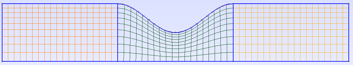 There is only one layer in the third dimension!  gmshToFoam: Code:
/*---------------------------------------------------------------------------*\
| =========                 |                                                 |
| \\      /  F ield         | OpenFOAM: The Open Source CFD Toolbox           |
|  \\    /   O peration     | Version:  4.1                                   |
|   \\  /    A nd           | Web:      www.OpenFOAM.org                      |
|    \\/     M anipulation  |                                                 |
\*---------------------------------------------------------------------------*/
Build  : 4.1
Exec   : gmshToFoam unchanges.msh
Date   : Apr 09 2017
Time   : 09:45:11
Host   : "ubuntu-labor"
PID    : 2776
Case   : /home/labor/openFoam/bachelor/1Vortest/1EinfacheGeometrie/2cavity
nProcs : 1
sigFpe : Enabling floating point exception trapping (FOAM_SIGFPE).
fileModificationChecking : Monitoring run-time modified files using timeStampMaster
allowSystemOperations : Allowing user-supplied system call operations

// * * * * * * * * * * * * * * * * * * * * * * * * * * * * * * * * * * * * * //
Create time

Starting to read mesh format at line 2
Read format version 2.2  ascii 0

Starting to read physical names at line 5
Physical names:6
    Surface 1	symmetryLine
    Surface 2	frontAndBack
    Surface 3	wall
    Surface 4	inlet
    Surface 5	outlet
    Volume 6	volume

Starting to read points at line 14
Vertices to be read:1160
Vertices read:1160

Starting to read cells at line 1177
Cells to be read:1671

Mapping region 2 to Foam patch 0
Mapping region 3 to Foam patch 1
Mapping region 1 to Foam patch 2
Mapping region 4 to Foam patch 3
Mapping region 5 to Foam patch 4
Mapping region 6 to Foam cellZone 0
Cells:
    total:513
    hex  :513
    prism:0
    pyr  :0
    tet  :0

CellZones:
Zone	Size
    0	513

Skipping tag  at line 2851
Patch 0 gets name frontAndBack
Patch 1 gets name wall
Patch 2 gets name symmetryLine
Patch 3 gets name inlet
Patch 4 gets name outlet

--> FOAM Warning :
    From function Foam::polyMesh::polyMesh(const Foam::IOobject&, const Foam::Xfer<Foam::Field<Foam::Vector<double> > >&, const cellShapeList&, const faceListList&, const wordList&, const wordList&, const Foam::word&, const Foam::word&, const wordList&, bool)
    in file meshes/polyMesh/polyMeshFromShapeMesh.C at line 595
    Found 1158 undefined faces in mesh; adding to default patch.
Finding faces of patch 0
Finding faces of patch 1
Finding faces of patch 2
Finding faces of patch 3
Finding faces of patch 4

FaceZones:
Zone	Size

Writing zone 0 to cellZone volume and cellSet
End
Code:
/*---------------------------------------------------------------------------*\
| =========                 |                                                 |
| \\      /  F ield         | OpenFOAM: The Open Source CFD Toolbox           |
|  \\    /   O peration     | Version:  4.1                                   |
|   \\  /    A nd           | Web:      www.OpenFOAM.org                      |
|    \\/     M anipulation  |                                                 |
\*---------------------------------------------------------------------------*/
Build  : 4.1
Exec   : checkMesh
Date   : Apr 09 2017
Time   : 09:46:39
Host   : "ubuntu-labor"
PID    : 2805
Case   : /home/labor/openFoam/bachelor/1Vortest/1EinfacheGeometrie/2cavity
nProcs : 1
sigFpe : Enabling floating point exception trapping (FOAM_SIGFPE).
fileModificationChecking : Monitoring run-time modified files using timeStampMaster
allowSystemOperations : Allowing user-supplied system call operations

// * * * * * * * * * * * * * * * * * * * * * * * * * * * * * * * * * * * * * //
Create time

Create polyMesh for time = 0

Time = 0

Mesh stats
    points:           1160
    internal points:  0
    faces:            2118
    internal faces:   960
    cells:            513
    faces per cell:   6
    boundary patches: 5
    point zones:      0
    face zones:       0
    cell zones:       1

Overall number of cells of each type:
    hexahedra:     513
    prisms:        0
    wedges:        0
    pyramids:      0
    tet wedges:    0
    tetrahedra:    0
    polyhedra:     0

Checking topology...
    Boundary definition OK.
    Cell to face addressing OK.
    Point usage OK.
    Upper triangular ordering OK.
    Face vertices OK.
    Number of regions: 1 (OK).

Checking patch topology for multiply connected surfaces...
    Patch               Faces    Points   Surface topology
    frontAndBack        1026     1160     ok (non-closed singly connected)
    wall                57       116      ok (non-closed singly connected)
    symmetryLine        57       116      ok (non-closed singly connected)
    inlet               9        20       ok (non-closed singly connected)
    outlet              9        20       ok (non-closed singly connected)

Checking geometry...
    Overall domain bounding box (0 0 0) (300 50 5)
    Mesh has 3 geometric (non-empty/wedge) directions (1 1 1)
    Mesh has 3 solution (non-empty) directions (1 1 1)
    Boundary openness (0 1.372194062e-17 1.15778874e-18) OK.
    Max cell openness = 1.51510062e-16 OK.
    Max aspect ratio = 3.217871397 OK.
    Minimum face area = 9.287696941. Maximum face area = 41.59656533.  Face area magnitudes OK.
    Min volume = 54.49465615. Max volume = 207.9828267.  Total volume = 68749.17972.  Cell volumes OK.
    Mesh non-orthogonality Max: 36.72623048 average: 10.84831016
    Non-orthogonality check OK.
    Face pyramids OK.
    Max skewness = 0.3384817772 OK.
    Coupled point location match (average 0) OK.

Mesh OK.

End
|
|
|
|
|
|
|
April 9, 2017, 07:31
|
|
#7 |
|
Senior Member
Alexey Matveichev
Join Date: Aug 2011
Location: Nancy, France
Posts: 1,930
Rep Power: 38 |
I believe, you missed step 4 from https://openfoamwiki.net/index.php/2...sh_to_OpenFOAM. I.e. gmsh do not store boundary types in mesh file, so after conversion, you have to correct boundary types of OpenFOAM mesh.
Moreover, in tutorial author makes plain 2D mesh (and gmsh file has misleading header comment), while for real simulation you need axi-symmetric 2D mesh, which should be done using a little bit different procedure (instead of plain extrusion, you need rotational extrusion; you need wedge patches instead of empty etc). |
|
|
|
|
|
|
April 9, 2017, 11:38
|
|
#8 |
|
Member
Teresa
Join Date: Nov 2015
Location: germany
Posts: 63
Rep Power: 10 |
Thank you very much! I totally misread that part and have now set the boundary correct. Mesh is 2D now and worked fine.
Sadly I do not understand the second part of your answer. What does the third dimension (type empty) has to do with the symmetryLine at the bottom? However I am not using it yet. Just made it "slip" to see if my other boundary conditions are set up correctly and work - which they do. Yay :-) |
|
|
|
|
|
|
April 9, 2017, 16:19
|
|
#9 |
|
Senior Member
Alexey Matveichev
Join Date: Aug 2011
Location: Nancy, France
Posts: 1,930
Rep Power: 38 |
Well, if you need just to run the case, then OK, there is no difference.
BUT if you would like to simulate real thing and maybe compare with experiment, you need to model flow inside a tube. And this can be achieved only using axial symmetry, while with empty patch and symmetryPlane you have plane symmetry (symmetryLine? did you mean symmetryPlane?). You can see the difference in the flow field in https://github.com/mrklein/foam-case.../stenosis/figs. |
|
|
|
|
|
|
April 10, 2017, 01:22
|
|
#10 |
|
Member
Teresa
Join Date: Nov 2015
Location: germany
Posts: 63
Rep Power: 10 |
Hey Alexeym,
no, I don't want to simulate the real thing. This case is just a learning experience. I say symmetryLine because that's the name of the symmetriyaxis-surface in the original File. The case is not about a tube but about a 2D Stenosis, therefore I would need to either mirror the mesh at the bottom or make it a SymmetryPlane to use it as intended. Maybe I will do that later. A tube, however, is not of big interest for now, as my ProjectCase is much more complex and I am looking for a 2D first and the 3D version would have a quadratic cross section not a circular. |
|
|
|
|
|
 |
| Tags |
| gmshtofoam 3d 2d gmsh |
|
|
 Similar Threads
|
||||
| Thread | Thread Starter | Forum | Replies | Last Post |
| [Gmsh] New version of gmshToFoam? | stootoon | OpenFOAM Meshing & Mesh Conversion | 7 | February 14, 2022 09:01 |
| [Gmsh] gmshToFoam problem. | nilashansen | OpenFOAM Meshing & Mesh Conversion | 11 | June 5, 2016 10:45 |
| [Gmsh] Cell to node connectivity after 'gmshToFoam' | Jibran | OpenFOAM Meshing & Mesh Conversion | 1 | June 8, 2015 09:09 |
| [Gmsh] gmshTofoam pbm with cyclicAMI | acahuzac | OpenFOAM Meshing & Mesh Conversion | 2 | October 20, 2014 03:53 |
| [Gmsh] gmshToFoam command | mvinassa | OpenFOAM Meshing & Mesh Conversion | 1 | April 25, 2014 07:36 |
 1Likes

 Linear Mode


