|
|
|
[Sponsors] | ||||
[OpenFOAM] Multiphase 3D free wave surface post-processing visualization in paraview |
 |
|
|
LinkBack | Thread Tools | Search this Thread | Display Modes |
 September 10, 2012, 18:14
|
|
#1 |
|
Senior Member
David Long
Join Date: May 2012
Location: Germany
Posts: 104
Rep Power: 13  |
Hi OpenFoamers,
I made a simple 3D multiphase case to test different ways of generating mesh (snappyHexMesh, blockMesh, Gmsh, etc). So far I am satisfied with the paraView, but I am still confused about how to visualize the free wave surface in 3D. 1. Free wave surface 3D damBreak case  Cull surface view 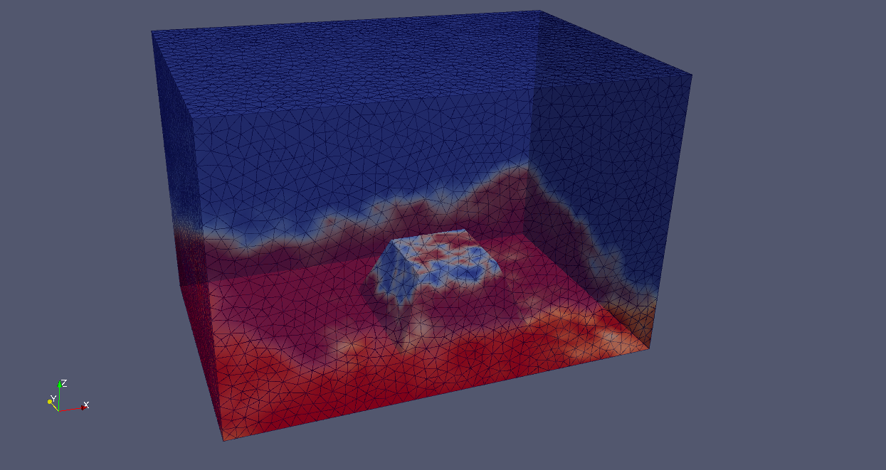 Transparent view We can see from the above figures, the water wave surface (aplha1 in this case) is basically in 2D, so I was wondering how do I make it in 3D like this:  2. Velocity field Since there are 2 phases (air & water), and the air velocity is much faster than the water velocity, so we can only see the result on top. 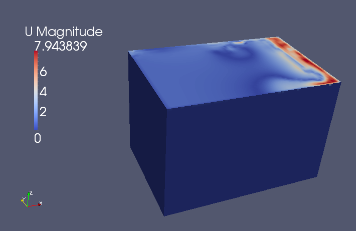 Is it possible to realize that only the water velocity field (vector or contour) visible? Because the velocity filed of water is of interest. Regards, David. |
|

|

|
|
|
September 11, 2012, 05:59
|
|
#2 |
|
Member
Jan
Join Date: Dec 2009
Location: Berlin
Posts: 50
Rep Power: 19  |
easily done!
1. Make sure your have the "internalMesh" loaded from the "Mesh Parts" 2. Also select "alpha1" to load from the "Volume Fields" Now use the "Threshold"-Filter with "alpha1". Use 0.5 for the "Lower Threshold" and 1.5 for the "Upper Threshold" (Although alpha should be in the range of 0 - 1 sometimes there are larger numbers than 1.) You should get a resulting surface that you can even make semi transparent with the "opacity"-setting under the display-tab. And of course you can set it to show the velocity. Greetings, Jan
__________________
~~~_/)~~~ |
|
|
|
|
|
|
September 11, 2012, 06:30
|
|
#3 | |
|
Senior Member
David Long
Join Date: May 2012
Location: Germany
Posts: 104
Rep Power: 13 |
Quote:
It seems that the "surface" is only an assemble of "blocks/cells", there is no interpolation between these blocks, how do you figure this out? 
|
||
|
|
|
||
|
September 11, 2012, 06:50
|
|
#4 |
|
Member
Jan
Join Date: Dec 2009
Location: Berlin
Posts: 50
Rep Power: 19 |
if you are only interested in the actual interpolated surface, then use the "contour" filter and set the value to 0.5
G Jan
__________________
~~~_/)~~~ |
|
|
|
|
|
|
September 11, 2012, 07:49
|
|
#5 | |
|
Senior Member
David Long
Join Date: May 2012
Location: Germany
Posts: 104
Rep Power: 13 |
Quote:
 there is still no smooth face  . .Thank you so much anyway. |
||
|
|
|
||
|
September 11, 2012, 09:03
|
|
#6 |
|
Senior Member
Martin
Join Date: Oct 2009
Location: Aachen, Germany
Posts: 255
Rep Power: 21 |
Hi David,
you can apply the "Filters->Alphabetical->smooth" filter with 200 iterations on the contour filter to improve the visualization. Martin |
|
|
|
|
|
|
September 11, 2012, 11:55
|
|
#7 | |
|
Senior Member
David Long
Join Date: May 2012
Location: Germany
Posts: 104
Rep Power: 13 |
Quote:
There is still an annoying problem, with regard to the " Smooth - number of iterations". As it increasing the surface becomes smoother, but when the number reaches up to around 500-1000, the surface does not get smoother, e.g. n=500, n = 1000 and n = 5000, you can not see big difference between them. At n = 1000, we can still notice the obvious edges on the surface. 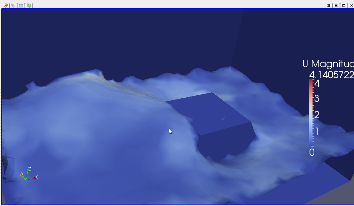 I looked up the para view manual, but unfortunately there is no such example about visualization such 3D surface. I wonder how you guys make this job done perfectly. Regards, David |
||
|
|
|
||
|
September 11, 2012, 12:07
|
|
#8 |
|
Senior Member
Martin
Join Date: Oct 2009
Location: Aachen, Germany
Posts: 255
Rep Power: 21 |
You can try to "subdivide" (Filters->Alphabetical->Subdivide) the smoothed interface and smooth the result again.
Or you can switch to an hexahedral mesh (with blockMesh) and with more elements. Martin |
|
|
|
|
|
|
September 11, 2012, 12:59
|
|
#9 |
|
Senior Member
Kent Wardle
Join Date: Mar 2009
Location: Illinois, USA
Posts: 219
Rep Power: 21 |
You have used the contour filter, which shows only the iso-surface for alpha=0.5, but you could also use the 'clip' filter instead and clip by the scalar alpha. This would show the full 'liquid' region. Again, you will still have the problem of interpolation on the surface and smoothing as you have done if you require it. If the surface is choppy, that just means your mesh should probably be refined for the simulation, no? Post-processing the surface to make it appear smoother is OK if you are just making a pretty picture, but...
Anyway, just wanted to suggest this as another option which may be useful since you would then from the clip have the liquid volume and could then use transparency (set opacity to less than 1) and make it look more like your example. Here is an example of my own with multiple clips (no post-smoothing) and opacity: 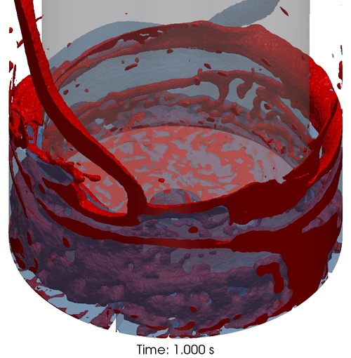 -Kent |
|
|
|
|
|
|
September 12, 2012, 08:48
|
|
#10 |
|
Senior Member
David Long
Join Date: May 2012
Location: Germany
Posts: 104
Rep Power: 13 |
thanks, kent.
It really helped. When the mesh is refined, the results look fantastic. -Daivd Last edited by keepfit; September 12, 2012 at 10:00. |
|
|
|
|
|
|
November 23, 2012, 13:21
|
|
#11 |
|
New Member
niall o sullivan
Join Date: Jan 2011
Posts: 2
Rep Power: 0 |
Hi David,
I am working on trying to implement an airflow over ocean waves which i have completed, i was wondering how you applied the airflow over the 3d dam break water surface. Thanks Niall |
|
|
|
|
|
|
December 21, 2012, 06:10
|
|
#12 | |
|
Senior Member
Dongyue Li
Join Date: Jun 2012
Location: Beijing, China
Posts: 838
Rep Power: 17 |
Quote:
Did you use MRFInterFoam simulating this? How many cells in your mesh? |
||
|
|
|
||
|
December 21, 2012, 09:46
|
|
#13 |
|
Senior Member
Kent Wardle
Join Date: Mar 2009
Location: Illinois, USA
Posts: 219
Rep Power: 21 |
This was done using multiphaseInterFoam, version 1.5.x. The mesh had ~2.5M poly cells (made in ccm+). More on this and related simulations in:
K. E. Wardle. "Open-Source CFD Simulations of LiquidLiquid Flow in the Annular Centrifugal Contactor," Sep. Sci. Technol. 46, 2409-2417 (2011). (doi:10.1080/01496395.2011.600748) |
|
|
|
|
|
|
December 21, 2012, 23:58
|
|
#14 | |
|
Senior Member
Dongyue Li
Join Date: Jun 2012
Location: Beijing, China
Posts: 838
Rep Power: 17 |
Quote:
I generated mesh via ICEM, but I can only make the solver working without exploding by the same mesh in ratate zone and stationary zone. for example: I generate block in the entire zone and name it seperately rotatezone the stationaryzone. then set the innerface as interior or interface. then run it by MRFInterfoanm it works. or just generate tow bodies called rotate and stationary. then compute mesh in unstructured mesh. It works too but a smaller time step. but problems arise when I am using hybird meshs. such as unstructured mesh in rotatezone and structured mesh in stationaryzone. There is always an innerface which can not be deleted. but this innerface should not emerge in the boundary dictionary.you can see it here http://www.cfd-online.com/Forums/ope...tml#post396032. but CFX or Fluent can handle this easily in their pre-process.while its tough in OpenFOAM. do you know how to handle this? by the way, you have so many cells, how small is your time step? and which program are you use to generate mesh? |
||
|
|
|
||
|
March 23, 2013, 11:57
|
|
#15 | |
|
Member
Guifan Li
Join Date: Apr 2011
Location: New York City, U.S.
Posts: 96
Rep Power: 15 |
Hi Kent,
Your work is quite good! Clip of scalar is a good guide for me. Just wondering if I am working on a case with two different phase, say , oil and water (oil droplet into water), do you think is there any way to visualize the simulation results? My case is like below, where I use contour to see the results. Quote:
|
||
|
|
|
||
|
March 25, 2013, 09:40
|
|
#16 |
|
Senior Member
Kent Wardle
Join Date: Mar 2009
Location: Illinois, USA
Posts: 219
Rep Power: 21 |
THANKS!
Have you tried using a scalar clip as I mentioned? This should work fine for your case assuming you are using an interFoam based solver and expect the phase interface to remain sharp. The image you have posted uses a contour so it only shows the single iso-surface for the given value. If you instead use a clip on the scalar you will get everything up to that value. I am not quite sure what you have shown in your image. You say oil droplet in water, but unless it is upside down or gravity is up, it looks like maybe you have instead a descending water drop in oil and a bulk water phase at the bottom that is not shown by the contour. |
|
|
|
|
|
|
March 25, 2013, 21:22
|
|
#17 | |
|
Member
Guifan Li
Join Date: Apr 2011
Location: New York City, U.S.
Posts: 96
Rep Power: 15 |
Hello Kent,
Thanks very much for the help and you really gave me a good way to start with. you are correct, the base is oil and the droplet is made of water. For the clip scalar, I am not sure what should I choose( alphas, alpha oil or alpha water?) to render and what value should I put ( I tried alphoil with value of 0.5 as in photes). Can you please explain how this value matters? if I use contour the result would be like the first photo I use three value 1.0 1.1 1.2 to make sure you can see the surface of the oil. The rest is to use the clip to scalar option BUT, only I can see the water-in red color when it falls into the oil, how can I see the effect like the one plotted by the contour but with different color? for Water-Base case I use the same method, but this time I can only see the water base but without and different colored oil on surface of the water. Wondering I chosen the wrong value for clip scalars, however, before knowing the mechanism, I am not sure what is right to choose..... Btw, the solver what I used is multiphaseEulerFoam Best regards, Quote:
|
||
|
|
|
||
|
March 28, 2013, 15:26
|
|
#18 |
|
Senior Member
Kent Wardle
Join Date: Mar 2009
Location: Illinois, USA
Posts: 219
Rep Power: 21 |
Well, it sort of depends on what you are actually trying to simulate which is still not super clear to me. If you have just the two phases (oil, water) AND you are using interfaceCompression between them (this can be switched off in multiphaseEulerFoam) then you could use a clip on the scalar alphawater (0.5 is fine) and then color as a solid color. For example, in your second image you have clipped by alphaoil but then colored by alphawater which isn't so useful if the interface is staying sharp. On the other hand, if you are mixing the two fluids Euler-Euler style (i.e. you have set the interfaceCompression coefficient for the (water oil) pair in constant/transportProperties to be 0) then you would want to color by the dispersed phase fraction. For example, here is an image from a recent paper (see this thread for links) in which I am simulating three phases (air, water, oil) but maintaining a sharp interface for air-water and air-oil only.
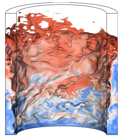 In this case, I have clipped by alphaair (I think I used a small value of 0.1 to capture more of the liquid near the spinning inner cylinder) and then colored the result by alphaoil. This is a full 360-degree model and so I also clipped in the vertical direction to show the cross-section. If what you are doing is simulating a droplet of water, initially suspended in oil, falling down into a water layer and impacting the oil-water interface then you should be able to get what you want by clipping by alphaoil=0.5 which will clip off everything that is on the oil side of the interface(s) and then color the remaining parts, which are now just water only as a solid color. -Kent |
|
|
|
|
|
|
March 30, 2013, 18:16
|
|
#19 | ||
|
Member
Guifan Li
Join Date: Apr 2011
Location: New York City, U.S.
Posts: 96
Rep Power: 15 |
Hi Kent,
I appreciated your very detailed explanation. To be more clear, what I am simulating is a droplet of oil about 0.6cm height with radius of 0.2cm, which is on top of pure water of 0.3cm height with 12 cm in radius. I am trying to view the results like the image you showed by clipping the alphaair with value of 0.1 and colored by alphaoil, however, it seems to be not working. As you can see. at t=0 Screenshot from 2013-03-30 19:01:40.jpg water+air+oil rendered Screenshot from 2013-03-30 19:00:46.jpg Only water base rendered Screenshot from 2013-03-30 18:59:04.jpg By using clip by alphaair=0.1, setting opacity =0.1 I use the Euler-Euler between water and oil setup as follow. Quote:
Screenshot from 2013-03-30 19:11:06.jpg Screenshot from 2013-03-30 19:11:24.jpg Quote:
|
|||
|
|
|
|||
|
March 30, 2013, 18:34
|
|
#20 | ||
|
Member
Guifan Li
Join Date: Apr 2011
Location: New York City, U.S.
Posts: 96
Rep Power: 15 |
continued..
Screenshot from 2013-03-30 19:11:49.jpg Screenshot from 2013-03-30 19:12:36.jpg Screenshot from 2013-03-30 19:12:50.jpg Apologize for the long post. but there are two things I am not clear are: In your paper, I saw your did use contactAngle setup. To be more realistic, I also would like to include them as well. Like in alphas file. Quote:
and in sigmas section, if I want to put surface tension of water is 0.07N/m, oil is 0.045N/m. Is this the correct way to define it? Quote:
|
|||
|
|
|
|||
|
| Thread Tools | Search this Thread |
| Display Modes | |
|
|
 Similar Threads
|
||||
| Thread | Thread Starter | Forum | Replies | Last Post |
| fluent DPM - post processing ParaView | gigivmasche | FLUENT | 4 | October 23, 2019 03:05 |
| Free Surface - Wave model - VOF | raquelcfd | STAR-CCM+ | 3 | September 26, 2018 03:11 |
| [waves2Foam] simulate a nonlinear regular wave: strange increase in free surface | Kun_zheng | OpenFOAM Community Contributions | 0 | January 19, 2018 10:42 |
| [General] Present the animation of water free surface around marine structure in Paraview | Lewis Liang | ParaView | 4 | May 14, 2017 03:33 |
| Free surface wave pattern generation | sam | FLUENT | 1 | January 2, 2004 16:12 |
 37Likes


 Linear Mode


