|
|
|
[Sponsors] | ||||
 July 11, 2012, 22:27
|
|
#1 |
|
New Member
Kons
Join Date: Apr 2012
Posts: 12
Rep Power: 13  |
Hey all,
this is my first post here in this forum so a big "Hello to all"  first of all. first of all.I have a problem I encounter with a DFBI Problem that I will try to describe: I have a catamaran in a box shaped domain. I am trying to model heave and pitch motions in headseas at zero speed. The domain is pitching with the catamaran. The thing is, when I look at the wave profile along the domain it seems like the coordinates are pitching as well. So as soon as the Cat/Domain starts to pitch the wave profile just gets really weird. So I dont really know how to fix this. I was hoping it was just a coordinate thing but now I am thinking it is due to the domain moving and not being able to resolve the waterprofile!? I attached some pictures of the wave profile along the domain and the mesh. Thanks for any thoughts on this!! cheers fuzel 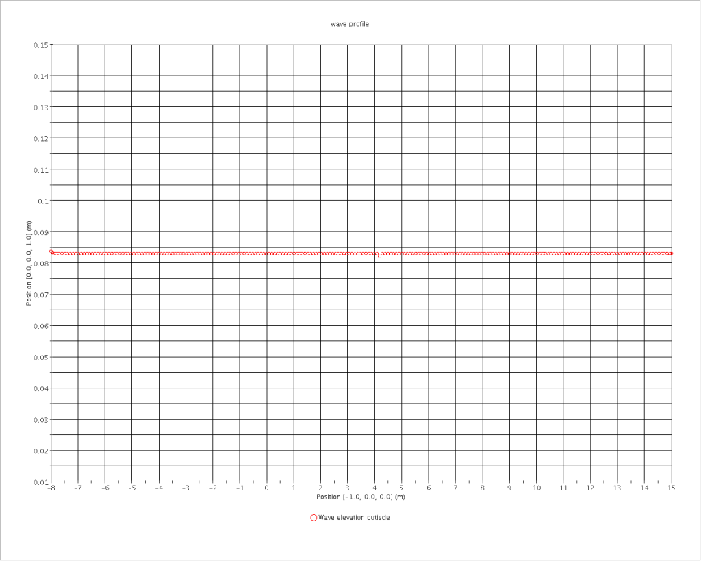 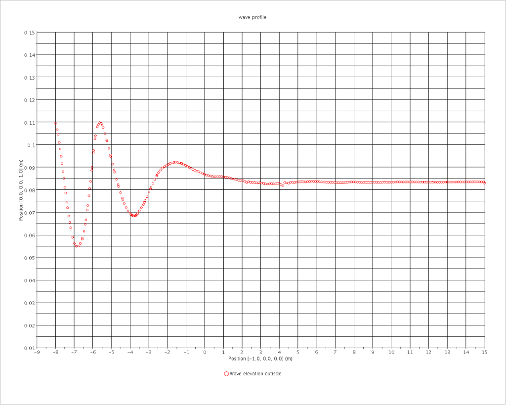 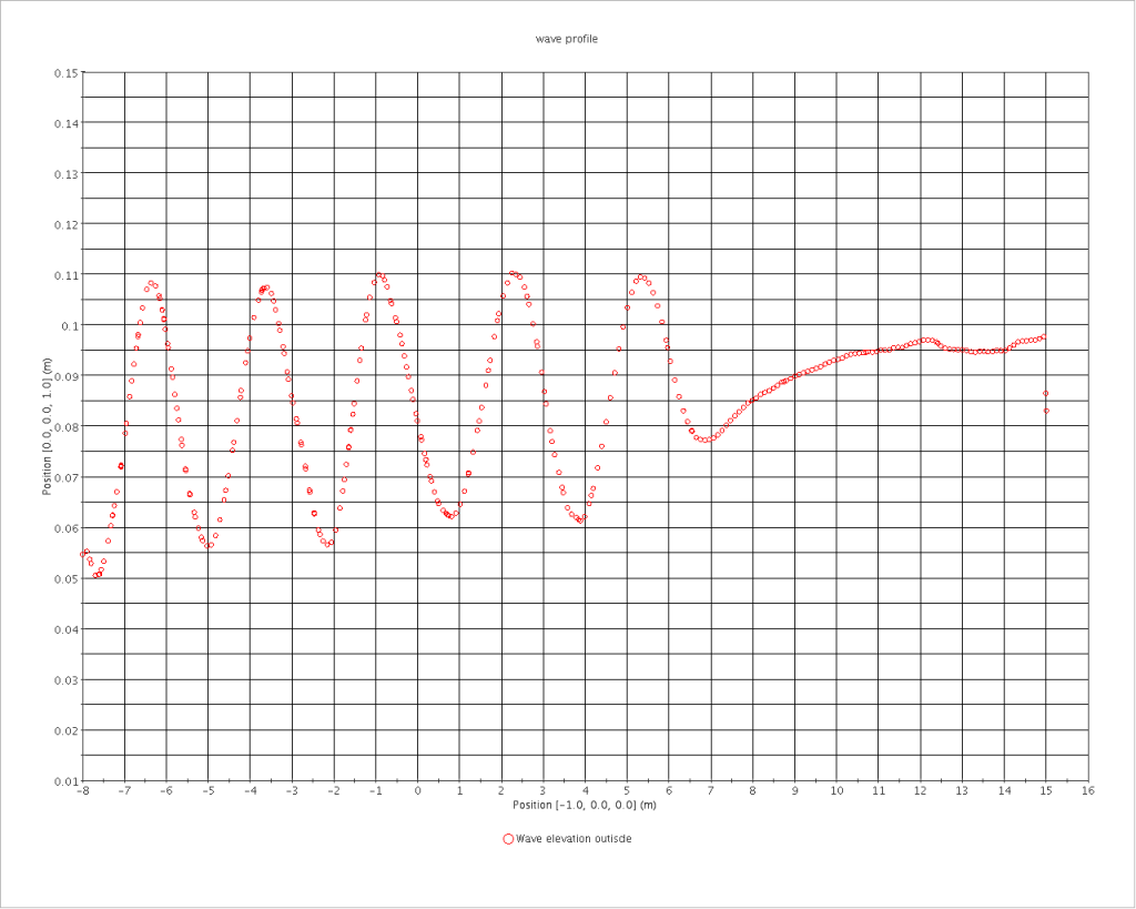 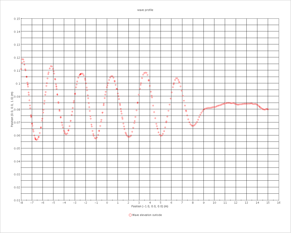 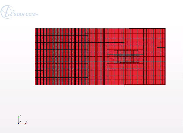 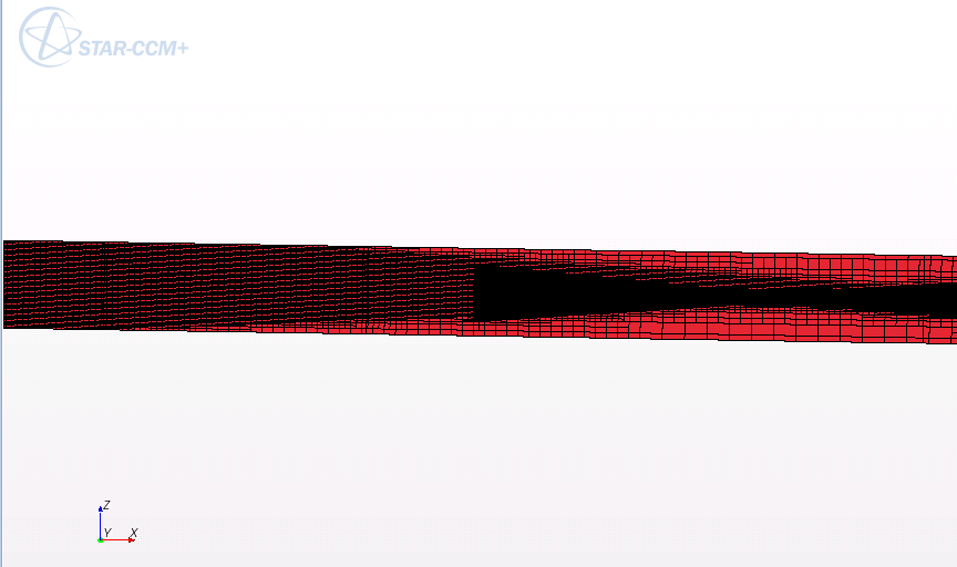
|
|

|

|
|
|
July 12, 2012, 02:06
|
|
#2 |
|
New Member
Kons
Join Date: Apr 2012
Posts: 12
Rep Power: 13 |
Well, I had a look at some other results from earlier.
Maybe this is useful information for understanding my problem. I did the same simulation with forward speed and the results are great. The differnce in mesh are that the domain for forward speed is a lot smaller. When I use the same for zero speed I get reflections from the back. So that's why I thought lengthening the domain would help. But probably DFBI with rotating domain is not a good option for long domains? Is there another way to get rid of the reflections? I noticed that for the smaller domain it was looking better when i defined the outlet as velocity inlet with wave field functions instead as pressure outlet!? Thanks again for any thoughts. |
|
|
|
|
|
|
July 12, 2012, 02:27
|
|
#3 |
|
Super Moderator

Alex
Join Date: Jun 2012
Location: Germany
Posts: 3,398
Rep Power: 46 |
I think I had a similar problem with a compressible LES in CCM+.
Reflections from the boundary conditions messed up the results. I wasn't able to resolve the problem because CCM+ still doesn't offer a non-reflecting boundary condition that really works. There are many "techniques" to get rid of reflections (coarsening the mesh before the outlet and inlet, damping fluctuations with a momentum source) but trust me: They do not work properly. |
|
|
|
|
|
|
July 12, 2012, 03:50
|
|
#4 |
|
Senior Member
KHB
Join Date: Aug 2010
Location: Singapore
Posts: 118
Rep Power: 15 |
As Alexander Stief described, you can either coarsening the mesh before the outlet and inlet, and use the Dampinb Boundary condition to damp the wave..
I did one simulation on a small domain with fixed trim and sinkage with and without the damping boundary condition, it helps to reduce the oscillation of the result for me.. The newest version of Star-CCM+ capable of doing overset mesh, have you tried? It will help you to reduce the mesh size since not the whole domain is rotating with it. |
|
|
|
|
|
|
July 12, 2012, 04:13
|
|
#5 |
|
New Member
Kons
Join Date: Apr 2012
Posts: 12
Rep Power: 13 |
Hey,
thanks for your ideas. The Mesh gradually gets coarser towards the outlet already. And I am just trying the damping as well at the moment. A question though: is the damping length you specify in starccm+ normal length from the boundary or in domain cooardinates? will i need to put -xy metres if my wave propagetes in -x direction? Another question: why do you want to coarsen the inlet region? In a free surface case that would kinda mess up my desired wave wouldn't it? Or did u mean for another case? I ll see what I can get out of overset mesh. Any tips on the meshing strategy? Do I mesh the domain with the free surface? and then the moving body with a bounding sphere? Thanks fuzel p.s: hope ill have some results tomorrow and will let you know what damping did for me |
|
|
|
|
|
|
July 12, 2012, 05:30
|
|
#6 |
|
Super Moderator
Alex
Join Date: Jun 2012
Location: Germany
Posts: 3,398
Rep Power: 46 |
Just to make this clear: damping zones and coarse meshes CAN, if applied with caution, reduce errors that are related to reflections.
Nevertheless, reflections WILL occur. In the case i investigated, these reduced reflections interacted with an acoustic mode in the computational domain and made the results useless, no matter how low the amplitude. About the damping at the inlet: that was just for the example i had in mind. |
|
|
|
|
|
|
July 12, 2012, 06:47
|
|
#7 |
|
New Member
Kons
Join Date: Apr 2012
Posts: 12
Rep Power: 13 |
Thanks flotus,
I put some different damping options on to run overnight. I ll see if that does the trick tomorrow but I am also not too optimistic. I also put an overset mesh on and see how that goes. I think that should give me some more freedom should it go allright. Specially when it comes to higher degrees in pitch or roll respectively. I ll keep you updated... Thanks again |
|
|
|
|
|
|
July 21, 2012, 04:52
|
|
#8 |
|
New Member
Kons
Join Date: Apr 2012
Posts: 12
Rep Power: 13 |
So i finally had time to have a look at my results. With a small domain and not too high pitch angles it worked well with introducing a damping function and having a coarser mesh in the region close to the outlet. I still get reflection after some time but the 25 seconds or so i get before they interfere with the incident wave are enough for my investigation.
However, when angles become to high or with a longer domain there seems to be a problem with the interpolation between the new position of the mesh and the old one. So I think a very small timestep might solve this but makes the computation unnecessary long. So I tried the oversetmesh approach which takes longer to compute but gives very good results even for high angles and/or a long domain and think that's the way to go. Thanks for your suggestions everyone! |
|
|
|
|
|
 |
| Thread Tools | Search this Thread |
| Display Modes | |
|
|
 Similar Threads
|
||||
| Thread | Thread Starter | Forum | Replies | Last Post |
| How to plot the wave contour in ship flow (free surface) problem | deddy1973 | CFX | 6 | February 19, 2013 05:49 |
| 2D Profile Data Initialization Problem for Transient Setup | deniz | CFX | 0 | July 10, 2012 05:43 |
| wave force problem | bojiezhang | FLOW-3D | 2 | January 17, 2011 20:01 |
| Problem with a leapfrog scheme for wave equation | Shiranui | Main CFD Forum | 0 | June 22, 2010 09:19 |
| VOF WAVE/ DFBI | MAB | FLOW-3D | 2 | November 14, 2008 00:02 |


 Linear Mode


