 |
|
|
[Sponsors] | |||||
|
|
|
#1 |
|
Member
Join Date: Oct 2015
Posts: 47
Rep Power: 10  |
Hi everyone!
I'm working on this turbocharger model and after having successfully generated a proper volume mesh (which took me ages) I'm now struggling with the simulation in itself. I'm using a moving reference frame to get the compressor wheel to rotate at 120,000 rpm. My volume mesh is valid according to the mesh diagnostics, but I still haven't managed to get the solution to converge. Depending on the selecting models and BCs, the residuals either stay constant around 10, or increase exponentially generating a floating point error. I've read here and there not to pay attention to residuals too much, but I'm pretty sure this isn't good news anyway  I understand the problem either comes from my mesh or from the physics (initial and boundary conditions). My model is pretty small, about 17cm long. I set my base size to 0.02m based on the inlet diameter. I then extracted the internal volume and meshed using the surface remesher and the polymesh, with a 2-layer prism layer mesher and a growth rate of 0.5, which gave me about 250k cells. Is it appropriate for a model this size? I'm not sure which solvers to use, because I've been reading all sorts of things about segregated/coupled flows, steady/unsteady states, k-e/k-w turbulence models... So I've tried them all, with different types of boundaries for the inlet (mass flow, velocity) and outlet (pressure, flow-split) and none of these solutions converged... I'm a bit lost in all this, could someone help me? Thanks a lot! Jambond |
|
|
|

|
|
|
|
|
#2 |
|
Senior Member
Matt
Join Date: Aug 2014
Posts: 947
Rep Power: 17  |
First, two prism layers is definitely not getting the job done. I have NEVER been able to get by with fewer than 5, typically 7 or more depending on the model. What are your wall y+ values? Are they appropriate for the turbulence/wall model you are using?
Second, how is this initialized? |
|
|
|

|
|
|
|
|
#3 |
|
Member
Join Date: Oct 2015
Posts: 47
Rep Power: 10  |
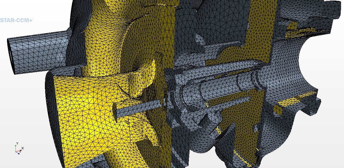
Thanks for your reply. I'm relatively new to CFD and wasn't familiar with wall y+ values so I read the documentation and started working on that. I've got the following problem now: while visualising my mesh on a plane section I realised the prism layer mesh doesn't apply to my fluid region at all, as you can see on this screenshot:
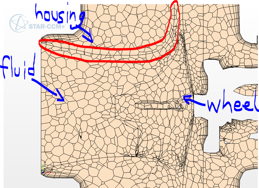 (interface between fluid and housing is circled in red) I precisely need the prism layer mesh at the interface between fluid and solid, where there actually is some air flowing, ie any kind of velocity... Right now my model is set up to display a velocity gradient at places there isn't any velocity at all. So it doesn't make sense. Is there a way to apply the prism layer mesher on my fluid region only? Do I have to make this a fluid-only simulation? Or maybe I could do without the prism layer mesher for now? Is it that important for the convergence? On the initialisation: I don't precisely know what you mean but I've gone for a k-e turbulence model with the standard dissipation rate and kinetic energy values, I split my fluid region by patch to create an mass flow inlet and a pressure outlet. I then chose an implicit unsteady model with a time step of 0.00008s which corresponds to 1/w, w being the rotation rate of my wheel. Other options are segregated flow, gas, constant density. Which gave me following residuals: 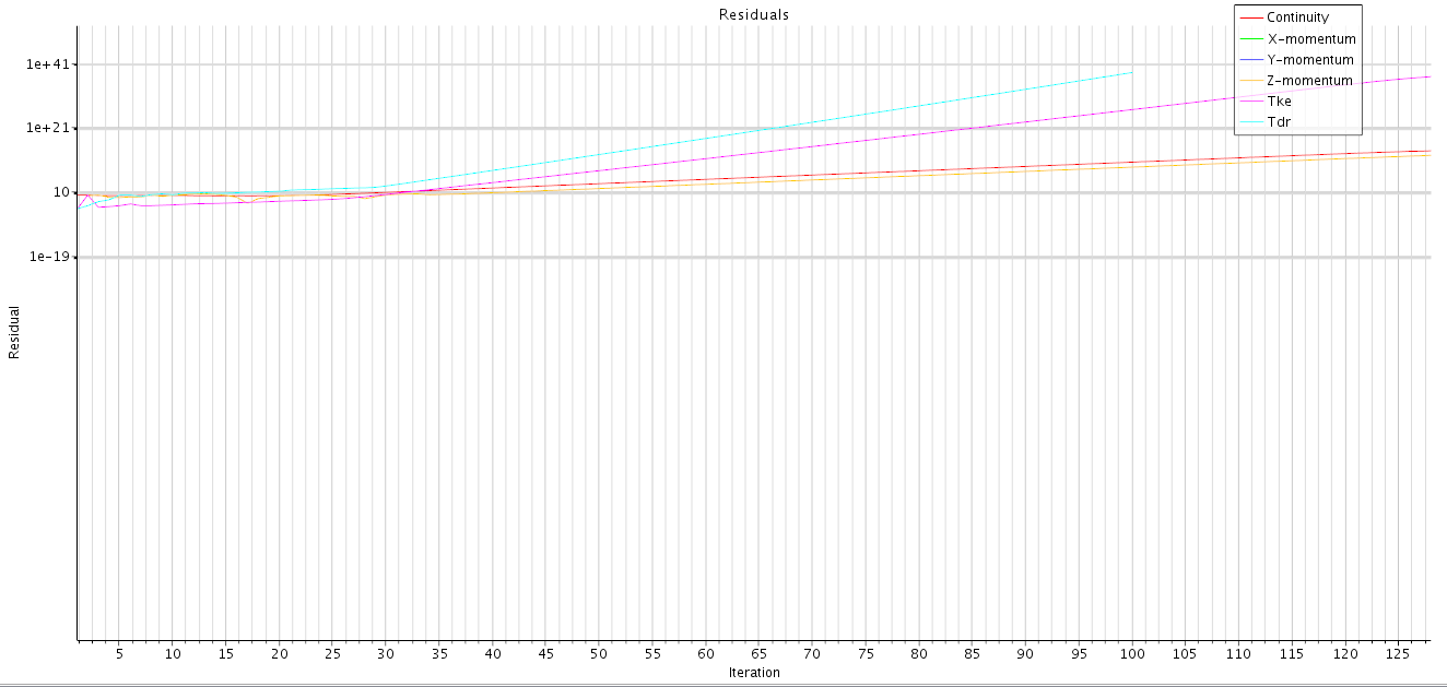 ... and a floating point error. Last edited by Jambond; February 2, 2016 at 10:43. |
|
|
|

|
|
|
|
|
#4 |
|
Senior Member
Matt
Join Date: Aug 2014
Posts: 947
Rep Power: 17  |
Y+ doesn't have anything to do with CAD. It is a measure of how well suited your near wall cells are for the boundary layer calculations you have selected.
It is quite obvious that you still have serious mesh issues. I am not even really sure what you are trying to show me in the picture, to be honest. Is the red circled region supposed to be a wall with prism layers growing from it? Can you show me a view of the geometry representation? Right-click in the scene and select Apply Representation > Geometry. |
|
|
|

|
|
|
|
|
#5 |
|
Member
Join Date: Oct 2015
Posts: 47
Rep Power: 10  |
Sorry it was a typo, I meant CFD...
Here are a couple pictures that should help you visualise the problem. First, a cross section view of my TC geometry under ProE: 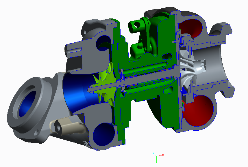 The left side of the TC is the one corresponding to my picture on my previous post, with the housing, the compressor wheel and of course the fluid flowing through all this. Now, as I explained before I extracted the internal volume on the compressor side. Here's what it looks like from the side in Star-CCM+: 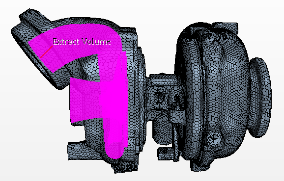 The extract volume should now be my fluid region, obviously. So if I understood the prism layer mesher correctly, the prisms should be on the edge of this fluid region (ie the pink extract volume), at the interface between the extract volume and the housing. Right? Thanks in advance for your help. |
|
|
|

|
|
|
|
|
#6 |
|
Senior Member
Matt
Join Date: Aug 2014
Posts: 947
Rep Power: 17  |
Correct, you should grow prism layers away from a wall into your fluid domain. They are not needed for meshing solids. My next question, are you trying to resolve thermal gradients in the solid parts too, or are you only interested in the behavior of the fluid?
All that aside, I can also recommend that you revisit your surface mesh. The volume mesh you show is nowhere near where it should be to resolve the geometry you have shown here. Most of the prism layers that are formed (and are directly related to surface mesh size) are junk. |
|
|
|

|
|
|
|
|
#7 |
|
Member
Join Date: Oct 2015
Posts: 47
Rep Power: 10  |
Okay, thanks for your reply, I'll look into this and will try to refine my surface mesh. I'll get back to you after that.
Meantime, could you explain me how to grow prism layers away from the housing wall into the fluid domain? And yes I'd be interested in the thermal behavior in the solid parts too, not just the fluid. |
|
|
|

|
|
|
|
|
#8 |
|
Senior Member
Matt
Join Date: Aug 2014
Posts: 947
Rep Power: 17  |
Prism layers will be created by the mesher if you have prism layer model selected for your mesh continua models. It looks like you already have this activated. They will automatically be created on any wall boundary in the fluid domain unless you deactivate the option under regions or region boundaries. What could be happening with you is that your surface mesh is too coarse and the prism mesher is failing to generate near wall cells. in that area. Again, without really seeing how you set it all up I can't say for sure.
I would suggest perhaps starting by analyzing the fluid domain then add the solids for thermal analysis once you have a good grasp on what it takes to solve the fluids side of things. |
|
|
|

|
|
|
|
|
#9 |
|
Member
Join Date: Oct 2015
Posts: 47
Rep Power: 10  |
Yes I think that would be an appropriate option for starters.
I'm working on my surface mesh right now and I found out I've been doing region-based meshing since the beginning (using the Generate surface and volume mesh buttons in the toolbar). Is it appropriate for a problem like this or should I switch to parts-based, which I'm not too familiar with? I can't really tell based on the documentation... |
|
|
|

|
|
|
|
|
#10 |
|
Senior Member
Matt
Join Date: Aug 2014
Posts: 947
Rep Power: 17  |
You should be fine with region based meshing. That is typically the approach I take, but I rarely have to do any thermal analysis.
|
|
|
|

|
|
|
|
|
#11 |
|
Senior Member
Gajendra Gulgulia
Join Date: Apr 2013
Location: Munich
Posts: 144
Rep Power: 13  |
Hi Jam,
I would suggest you to split the continua in multiple regions, and apply tighter mesh controls in regions where flow phenomena changes. For example the inlet region, narrow region and the rear region. Have internal interfaces b/w the boundaries (don't forget to switch off the prism layer at interfaces) Under the surface repair of import data, make sure that your surface penetration (the parameter that is highlighted as red in surface repair) is zero. Similarly in the remeshed representation, all the 6 parameters should be zero. This indicates a decent surface quality for having a volume mesh Secondly I recommend you to use the mesh controls in polyhedral mesh and prism mesh (see the documentation) to have better controls over the mesh growth. |
|
|
|

|
|
|
|
|
#12 |
|
Member
Join Date: Oct 2015
Posts: 47
Rep Power: 10  |
I'm currently trying to refine the wheel area, but I'm having trouble...
I'm doing region based meshing, so I'm using the Relative minimum size and Relative target size in my "wheel" boundary properties. Here's what I get when I'm trying to mesh the wheel alone: 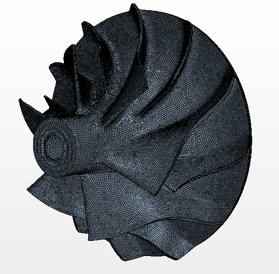 And here's what I get with the same settings but when meshing all the parts together: 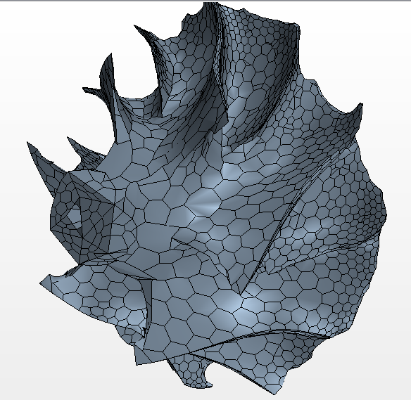 So clearly the other parts (maybe the Extract volume surrounding the wheel) are messing with the refinement, but I can't find a way to fix it... Any thoughts? |
|
|
|

|
|
|
|
|
#13 |
|
Senior Member
Matt
Join Date: Aug 2014
Posts: 947
Rep Power: 17  |
All problems lie in your surface mesh. Are you generating a surface mesh before you generate a volume mesh? Can you show this to me? So far you have only shown me a volume mesh and it looks like all of your issues in the volume can be traced back to surface.
|
|
|
|

|
|
|
|
|
#14 |
|
Member
Join Date: Oct 2015
Posts: 47
Rep Power: 10  |
Sure, here are a few views of the surface mesh, I don't know if they're relevant enough:
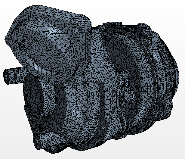 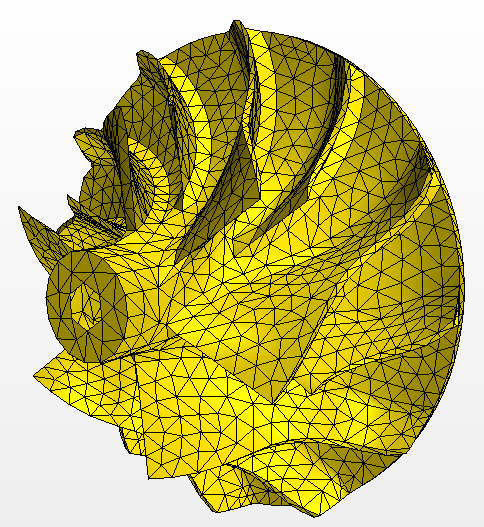 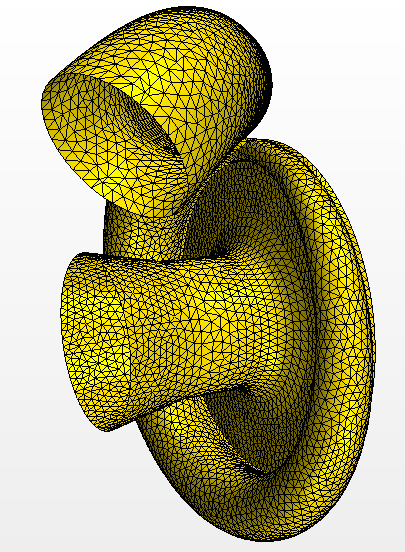  I've tried to focus on the wheel as it's the most complex of my parts. I've tried out several values for the relative minimum size and the relative target size of the surface remesher with 3 different base sizes (0.01 - 0.02 - 0.03m) and had a look at the mesh in the wheel area for each one of them. Here are a few examples of the output meshes: 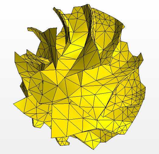 Base size = 0.02m, Relative min size = 25% of base, Relative target size = 100% of base (standard values) 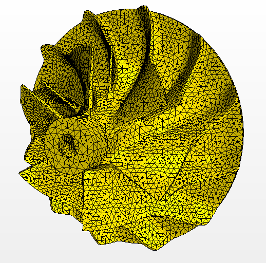 BS=0.02 ; RMS=5% ; RTS=10% 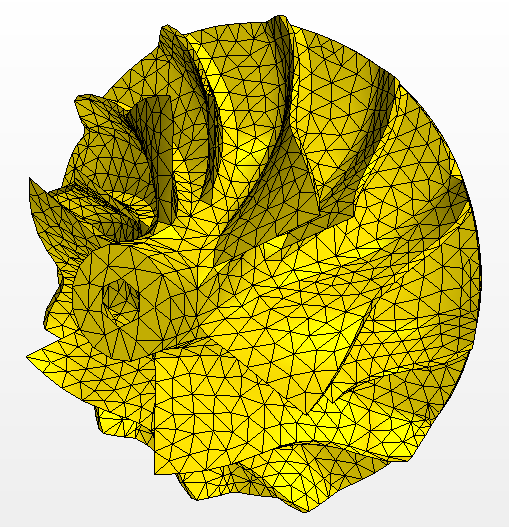 BS=0.02 ; RMS=10% ; RTS=25% 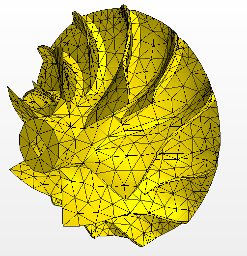 BS=0.03 ; RMS=10% ; RTS=25% 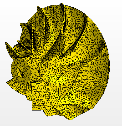 BS=0.01 ; RMS=10% ; RTS=25% So as a conclusion I found the parameters BS=0.02m; RMS=10% of base; RTS=25% of base to be proper values based on how the mesh looked. Problem is, the volume mesh generation is failing with these values because of sharp dihedral angles. I then tried several imprint tolerance values to fix this but none of them got me a volume mesh. I'm gonna keep digging a bit but can you tell me if I've done something wrong so far? And what I can try next? Maybe other parameters/functions? Thanks a lot! |
|
|
|

|
|
|
|
|
#15 |
|
Senior Member
Matt
Join Date: Aug 2014
Posts: 947
Rep Power: 17  |
Are you using a single set of target/min values globally? Your model certainly warrants using custom controls.
Right-click, Geometry > Operations > Automated Mesh > Custom Controls, Select New > Surface Controls and assign parts/surfaces individually to give a more tailored surface mesh. Very rarely can you get away with a global set (default controls) only. |
|
|
|

|
|
|
|
|
#16 |
|
Member
Join Date: Oct 2015
Posts: 47
Rep Power: 10  |
Okay I'll try this out tomorrow. I haven't been using the surface remesher as an operation so far, will this be a problem? That's why I was asking about parts/region based meshing before.
|
|
|
|

|
|
|
|
|
#17 |
|
Senior Member
Matt
Join Date: Aug 2014
Posts: 947
Rep Power: 17  |
Shouldn't matter, although, I am not sure that constitutes parts based meshing. If you were applying volume mesh under geometry > operations then, yes. That would be parts based meshing. Maybe this is some kind of bastardized hybrid. I have attached the workflow I use. It works well for me, but there is certainly more than one way to approach things.
|
|
|
|

|
|
|
|
|
#18 |
|
Member
Join Date: Oct 2015
Posts: 47
Rep Power: 10  |
Alright, thanks for the tip!
Since I was doing region based I went ahead and applied the modifications in the Regions node. eg: Regions > Wheel > Boundaries > Wheel > Mesh conditions > Custom Surface size > Enable, and then Mesh Values > Relative minimum/target size. This should do exactly the same as what you were suggesting right? Ie applying local mesh values to a particular boundary. Anyway I did this and it absolutely didn't work out. Best I can get in terms of aspect is this: 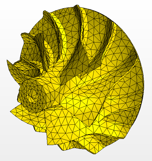 And I can't get a volume mesh out of this, obviously. Should I then try your way, with the Automated mesh operation? I doubt it would gave me better results... But I can try. |
|
|
|

|
|
|
|
|
#19 |
|
Senior Member
Matt
Join Date: Aug 2014
Posts: 947
Rep Power: 17  |
It definitely will work the way I described, should have worked the way you did it. Just do the surface mesh and inspect, don't waste time on a volume mesh until you have a surface mesh you like. You can execute them independently. You may have several iterations of trying different values, but it will work. I promise.
|
|
|
|

|
|
|
|
|
#20 |
|
Member
Join Date: Oct 2015
Posts: 47
Rep Power: 10  |
So I tried your way, and I'm still a bit confused.
I launched an automated surface mesh alright, with proper settings, until I got this for the wheel: 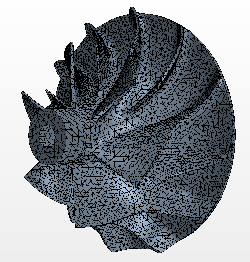 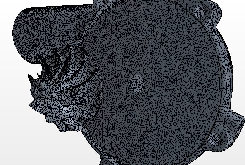 I think it looks fairly good. So now I have to generate a volume mesh from this, and that's where I'm not sure how to follow the workflow. The way I see it, there's two ways to do this. 1/ By checking a volume mesher (eg. polyhedral) in the Automated mesh options 2/ By creating a mesh continuum and checking polyhedral mesher Once I've created a surface mesh via the Automated mesh operation, it would make sense to go with option 1; however your workflow suggests I should create a continuum and click "generate volume mesh"... So I' confused. How do you precisely proceed? I tried to stick to your thing and checked surface remesher (only) in Automated mesh, and polyhedral (only, no surface remesher) in Continua > Mesh. It failed, and the reports reads following: ---------------------------------------- Surface Remesher Completed: CPU Time: 293.20, Wall Time: 293.20, Memory: 3815.68 MB ---------------------------------------- ---------------------------------------- Automated Mesh Operation: Automated Mesh complete. CPU Time: 500.98, Wall Time: 500.98, Memory: 2025.77 MB ---------------------------------------- Transferring geometry for meshing. Executing parts-based surface mesh operations Executing region-based surface meshers... No region-based surface meshers selected. No solution currently computed -- clearing volume mesh. Preparing surface for volume meshing in regions: Extract Volume, HITZESCHILD_TURBINE, LAGERGEHAEUSE, TURBINE_MOD, TURBINEN_DECKEL, VERDICHTER_DECKEL, VERDICHTERGEHAEUSE, VERDICHTERRAD Error during volume meshing, deleting resulting mesh Object of requested type "class FvRegionManager" does not exist in manager "Simulation>RepresentationManager>FvRepresentation ("Volume Mesh")>TypedObjectManager" Command: GetProperties Recoverability: Non-recoverable An edge attached to Boundaries: Default, VERDICHTER_DECKEL.Default [Extract Volume/VERDICHTER_DECKEL], VERDICHTER_DECKEL.fill1 [Extract Volume/VERDICHTER_DECKEL 2] is attached to an odd number of faces (5). Check surface and interface definitions on these boundaries before proceeding. Command: GenerateVolumeMesh error: Server Error So if I go by the part in bold in the report, there clearly is a confusion between parts based and region based... Which makes me think I should choose between option 1 and 2 but by no means mix the two. Anyways, maybe it's not the heart of the problem. I then went ahead and tried to generate a volume mesh using the Automated mesh operation, and I got this "odd number of faces" error EVERY TIME. I'm really fed up with this, I don't understand where the problem comes from... I read here and there it had something to do with the imprint but I've been trying every possible values and all of them failed. So now I have a good looking surface mesh, at least I think I do, but I'm getting nowhere with it. Maybe I can send you my sim file if you've got some time? The end of my project is closing in and I don't even have a proper mesh...  Thank you! |
|
|
|

|
|
 |
|
|
 Similar Threads
|
||||
| Thread | Thread Starter | Forum | Replies | Last Post |
| grid dependancy | gueynard a. | Main CFD Forum | 19 | June 27, 2014 21:22 |
| Naca 0012 (compressible and inviscid) flow convergence problem | bipulsaha | FLUENT | 1 | July 6, 2011 07:51 |
| Solution Does Not Converge | Rif | Main CFD Forum | 3 | March 7, 2008 05:33 |
| My Solution wont Converge!!! | Chris | FLUENT | 6 | April 16, 2005 18:57 |
| Wall functions | Abhijit Tilak | Main CFD Forum | 6 | February 5, 1999 01:16 |