|
|
|
[Sponsors] | ||||
 February 24, 2012, 23:57
|
|
#1 |
|
New Member
Matt
Join Date: Feb 2012
Location: Mankato, MN - St. Louis, MO
Posts: 12
Rep Power: 14  |
Hi,
I am modeling the mixture of methane being injected into an intake track for a small 3 cylinder diesel engine using the multi-component flow feature. I used the tutorial as my guide to set it up correctly. However, I originally had it set up to do Mass flow inlet (instead of velocity inlet) for both my air inlet and my gas inlet. And I had flow-split outlet for the three outlets of my intake manifold. I used the given number (in the tutorial) for the dynamic viscosity (1.175E-5 Pa-s) of the methane gas. After everything was set up and I went to run it, it gave me a lengthy error that pretty much said the viscosity value wouldn't work. So I thought, that makes sense, my pressure and temperature is different than in the tutorial. I calculated a rough value for the current viscosity and it still gave me the same error. I played around with a few different values thinking I just didn't calculate it right and then it started giving me this error "error a floating point exception occurred: floating point exception [invalid operation]". So then I tried setting up the inlets as a velocity inlet (as done in the tutorial, with my calculated velocities and temperatures, not those used in the tutorial) with flow split outlets, and I got the same error. I tried again with with the dynamic viscosity value they gave; same error. I tried again with velocity inlets, and a Pressure Oulets, just as the tutorial is...same error. I'm a noob and have run out of things to try. Could it really be just a wrong dynamic viscosity number causing problems? Something else I need to do? thanks alot! Matt |
|

|

|
|
|
March 1, 2012, 08:13
|
|
#2 |
|
Senior Member

siamak rahimi ardkapan
Join Date: Jul 2010
Location: Copenhagen, Denmark
Posts: 220
Rep Power: 17 |
It could be because of the quality of mesh. check the quality of your mesh. Try to reduce the under relaxation factor in the solvers. It may work. If you run unsteady, then it is wise if you reduce the time step also. good luck
|
|
|
|
|
|
|
March 2, 2012, 14:35
|
|
#3 |
|
New Member
Matt
Join Date: Feb 2012
Location: Mankato, MN - St. Louis, MO
Posts: 12
Rep Power: 14 |
Thanks for the reply.
I was able to get it to run a simulation. I want to look at mass faction of Methane in my air. I want to use streamline to visualize. I am having hard time getting it to work. If I set it to part seed, and my U and V are set too high, it just shows all blue (all air) If it turn it way down, theres like 2 streamlines, but does show color contrast. If I use line seed, if I put it straight across the intake it'll show alot of lines, alot of turbulence, and a different color contrast if I put it at other location. I know I'm not phrasing this very well and its because I really don't understand how the streamline settings work I guess, and thus, why this isn't working. How it can change mass fraction for my already given parameters? |
|
|
|
|
|
|
March 14, 2012, 01:03
|
|
#4 |
|
New Member
Matt
Join Date: Feb 2012
Location: Mankato, MN - St. Louis, MO
Posts: 12
Rep Power: 14 |
I guess a better question would be, can someone explain to me how the streamlines work, what the U and V actually mean? That way I might be able to figure it out.
Thanks. |
|
|
|
|
|
|
March 14, 2012, 03:35
|
|
#5 |
|
Senior Member
siamak rahimi ardkapan
Join Date: Jul 2010
Location: Copenhagen, Denmark
Posts: 220
Rep Power: 17 |
If you look at the field functions, you will see the functions created for every phase ( like flow rate of particle and so on). just add the function that you need to the vector scene for example.
|
|
|
|
|
|
|
March 15, 2012, 12:26
|
|
#6 |
|
Senior Member
Robert
Join Date: Jun 2010
Posts: 117
Rep Power: 16 |
If you can read the streamline source position help and figure it out you are a better/smarter man than I am.
I am not sure whoever wrote it (either the code or the help) has ever tried it on a generalized 3 D example. |
|
|
|
|
|
|
March 19, 2012, 22:31
|
|
#7 |
|
New Member
Matt
Join Date: Feb 2012
Location: Mankato, MN - St. Louis, MO
Posts: 12
Rep Power: 14 |
Yeah, you're right, I really don't know.
Below are screen shots of whats going on.  you can see here that at U of 2 and V of 8, It shows a varying mass fraction, but with very few streamlines 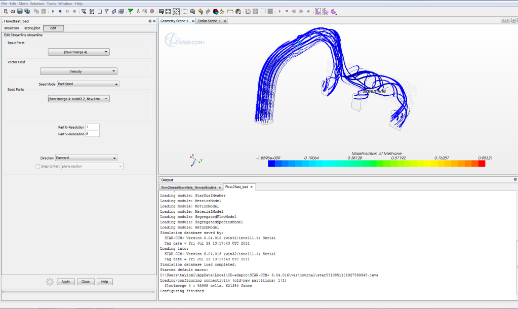 Here I make U 3, and no mass fraction variation. I really don't get why... |
|
|
|
|
|
|
March 21, 2012, 06:05
|
|
#8 |
|
Senior Member
Join Date: Oct 2009
Location: Germany
Posts: 636
Rep Power: 21 |
U and V are just the number of streamlines in two directions along your seed part. Choosing a different x or y resolution doesn't change your solution. Just the visualisation changes.
One explanation: Did you see the difference for the maximum mass fraction in your two pictures? Having more or less streamlines also changes the position of the streamlines. In the second pictures, one streamline seems to cross a cell with a very high mass fraction (might be due to physical or numerical reasons, but one single cell is enough), therefore the max mass fraction is very high. And all streamlines SEEM to be have a lower mass fraction, but they are just blue due to the different scale. So fix the maximum mass fraction in the streamline displayer to an intermediate value, let's say 0.025 or so. And then compare the streamlines. They should look the same ish. By the way, I think the high mass fraction in at least one cell is due to numerical values (bad mesh, bad boundary conditions etc). Why do I think this? Well, the minimum scale in the second pictures has a negative value. That can't be physical and is suspicious. Therefore I think that maybe the mesh contains some bad cells which might cause an unphysical high mass fraction and the (obviously) high gradients. |
|
|
|
|
|
|
July 7, 2013, 11:08
|
|
#9 |
|
New Member
Join Date: Jan 2011
Posts: 6
Rep Power: 15 |
Just got the same problem. Simulation failed and a window pumped saying some floating issues. It is the multi-compoenents model because everything works at the same simulation before it is activated..So, why could it happen?
And I am amused by initialization fails when the sum of mass fraction is zero 
|
|
|
|
|
|
|
July 9, 2013, 14:14
|
|
#10 |
|
New Member
Join Date: Jan 2011
Posts: 6
Rep Power: 15 |
solved. Simulate the bulk phase first and then switch to multicomponent flow.
|
|
|
|
|
|
|
March 12, 2016, 12:43
|
|
#11 |
|
New Member
Kanwar
Join Date: Feb 2016
Posts: 6
Rep Power: 10 |
How do you do that?
|
|
|
|
|
|
 |
| Thread Tools | Search this Thread |
| Display Modes | |
|
|
 Similar Threads
|
||||
| Thread | Thread Starter | Forum | Replies | Last Post |
| Multi Component Flow Modeling | bmatsuo | ANSYS | 0 | June 23, 2011 20:13 |
| Add total mass using sources to multi component fluids | mullenc525 | CFX | 1 | February 5, 2011 04:56 |
| multi fluid mixture model issue | rystokes | CFX | 3 | August 9, 2009 19:13 |
| multi component diffusivity | mahut | FLUENT | 0 | October 10, 2007 04:05 |
| modeling a mixture of gases | franciscotovar | CFX | 0 | October 17, 2006 12:41 |
 1Likes


 Linear Mode


