|
|
|
[Sponsors] | ||||
Difference in Visualization of q criterion in tetra and hexa mesh |
 |
|
|
LinkBack | Thread Tools | Search this Thread | Display Modes |
 April 23, 2018, 00:30
|
|
#1 |
|
Senior Member
raunak jung pandey
Join Date: Jun 2016
Posts: 102
Rep Power: 9  |
I am carrying out a simulation of external flow using SST model. I carried out simulation using both tetra and hexa mesh. The y+ =1 on the external flow and node number is 2.9 million.
Simulations are carried out with same boundary conditions. But tetra mesh shows different results near the boundary layer which is not present in hexa mesh. If some one has experience carrying out such simulation please suggest what is happening ? Thank you this is results with tetra mesh 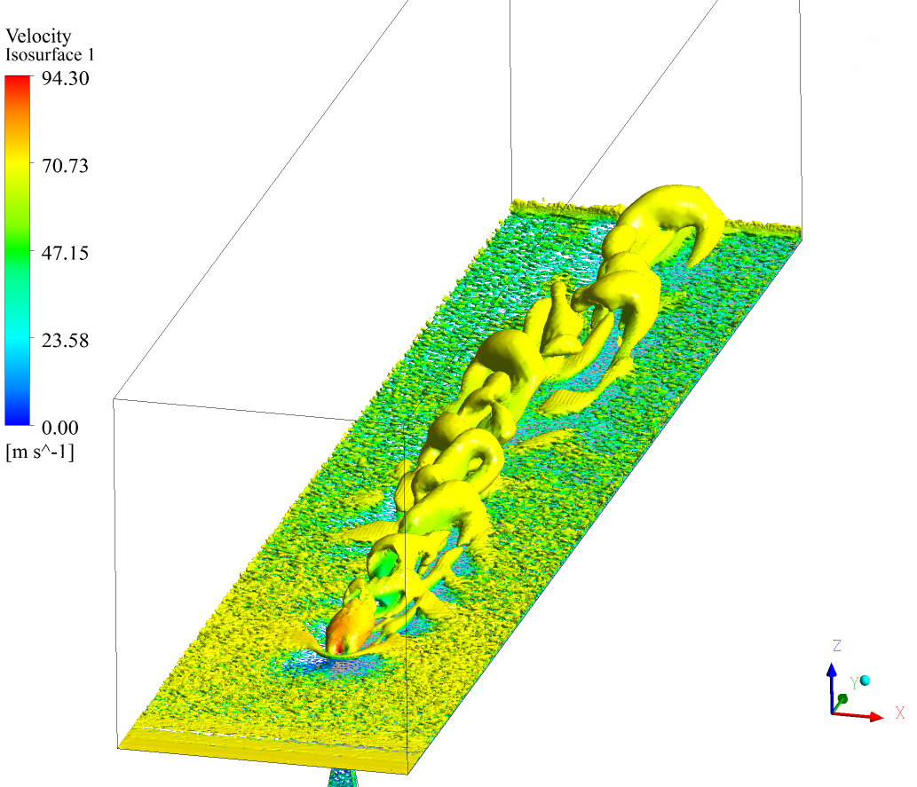 this is results with hexa mesh 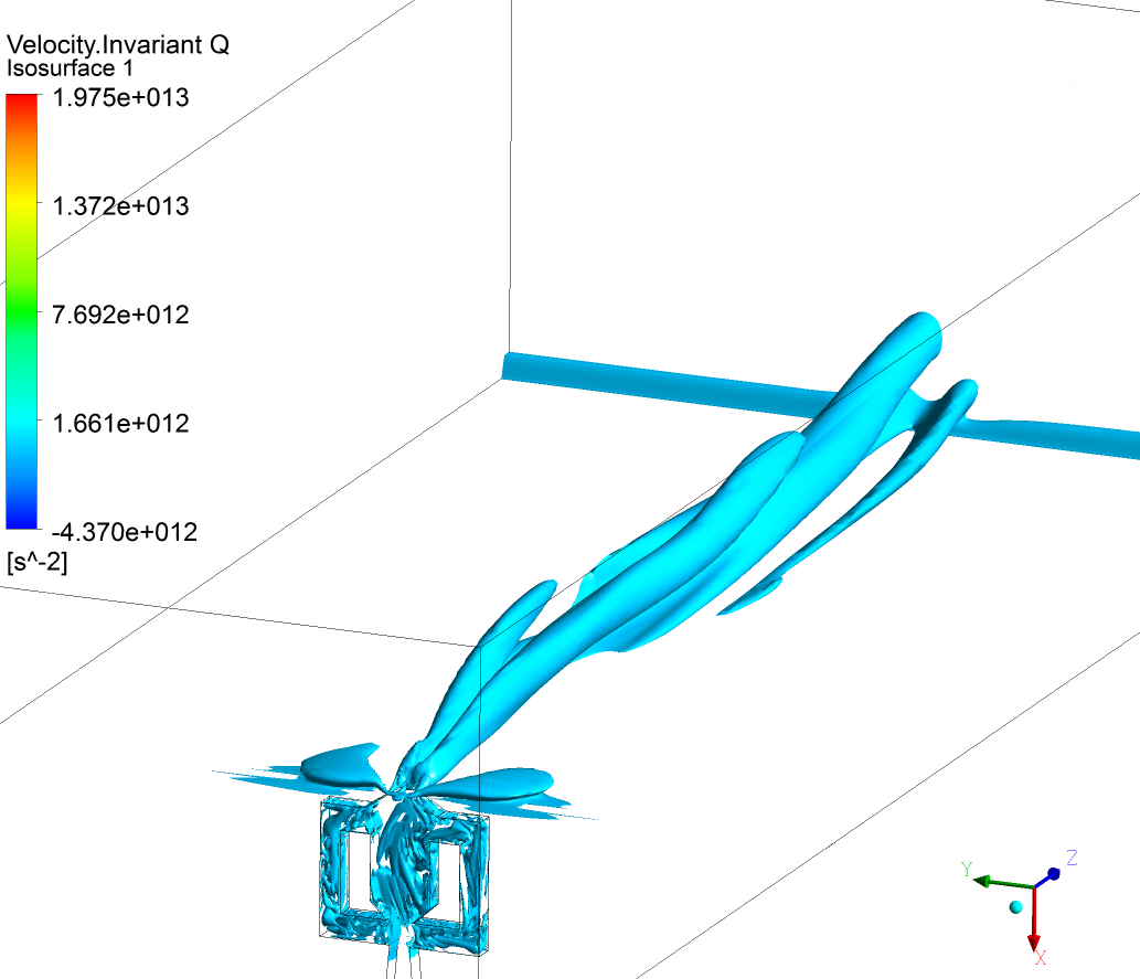
|
|

|

|
|
|
April 24, 2018, 18:43
|
|
#2 |
|
Senior Member
Lucky
Join Date: Apr 2011
Location: Orlando, FL USA
Posts: 5,674
Rep Power: 65 |
Are you even comparing apples to apple?
The top plot is presumably the isosurface of Q=0? colored by velocity magnitude? Then why is the bottom plot of "Velocity.InvariantQ" having units 1/s^2 and having magnitudes (10^12) that do not look like velocities? And the flow is going along a different axis. Sorry but it seems there is a lot more going on here. |
|
|
|
|
|
|
April 24, 2018, 21:37
|
|
#3 |
|
Senior Member
raunak jung pandey
Join Date: Jun 2016
Posts: 102
Rep Power: 9 |
Thank you for replying.
The top plot is not iso surface at Q=0. both the iso surfaces have been drawn at Q= 500,000 s-2. In the top plot the isosurface exists in higher Q also. The bottom isosurface is not colored by velocity magnitude hence. Please neglect the axis right now. The boundary conditions remains same for both simulations. The difference is only the mesh used. Upper being tetra and latter is hexa. Check in this figure. The Q originating from the device to the external domain is different. 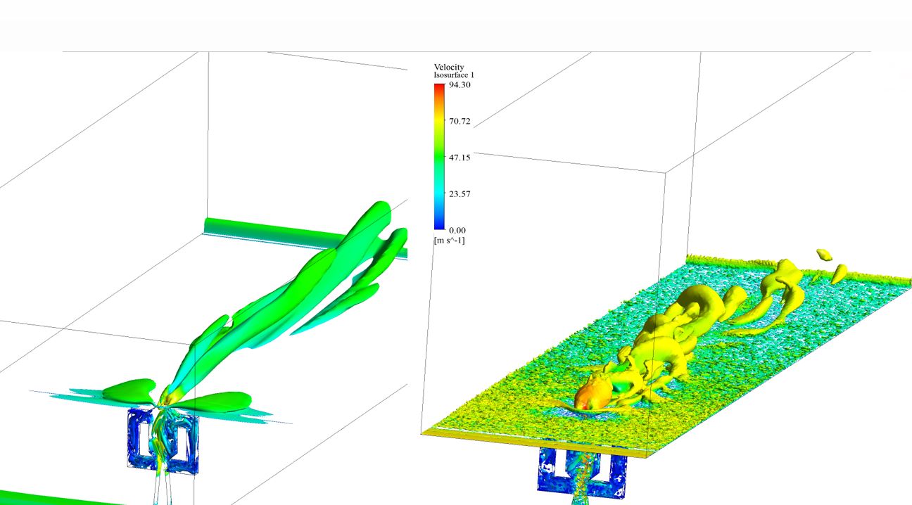
|
|
|
|
|
|
|
January 10, 2021, 05:15
|
|
#4 |
|
New Member
Juanjo
Join Date: Jan 2021
Posts: 1
Rep Power: 0 |
Mr raunakjun, did you manage to understand what was going on?
I am currently performing external flow simulations wih hex mesh, but my Q-criterion representations are more similar to your tetahedral simulation. |
|
|
|
|
|
|
|
|
 Similar Threads
|
||||
| Thread | Thread Starter | Forum | Replies | Last Post |
| [ICEM] Creation of hexa dominant mesh and prism layer | gnuboard | ANSYS Meshing & Geometry | 7 | January 11, 2018 04:13 |
| [ICEM] Unstructured Tetra Mesh around Structured Hexa Mesh | grinser92 | ANSYS Meshing & Geometry | 0 | April 12, 2017 15:05 |
| [ICEM] Hybrid mesh hexa and tetra on ICEM | PeterDaniel | ANSYS Meshing & Geometry | 0 | October 22, 2013 12:22 |
| tetra hexa mesh | hamid1 | FLUENT | 5 | April 12, 2012 11:23 |
| Solution on hexa mesh vs solution on tetra mesh | Chander | CFX | 2 | December 10, 2011 09:35 |
 Linear Mode


