Turbulence intensity
From CFD-Wiki
(minor corrections) |
m |
||
| (44 intermediate revisions not shown) | |||
| Line 1: | Line 1: | ||
==Definition== | ==Definition== | ||
| - | The turbulence intensity is defined as: | + | The turbulence intensity, also often refered to as turbulence level, is defined as: |
| - | :<math> | + | :<math>I \equiv \frac{u'}{U}</math> |
Where <math>u'</math> is the root-mean-square of the turbulent velocity fluctuations and <math>U</math> is the mean velocity ([[Reynolds averaging|Reynolds averaged]]). | Where <math>u'</math> is the root-mean-square of the turbulent velocity fluctuations and <math>U</math> is the mean velocity ([[Reynolds averaging|Reynolds averaged]]). | ||
| Line 9: | Line 9: | ||
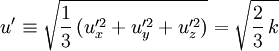
If the turbulent energy, <math>k</math>, is known <math>u'</math> can be computed as: | If the turbulent energy, <math>k</math>, is known <math>u'</math> can be computed as: | ||
| - | :<math>u' = \sqrt{\frac{2}{3}\, k}</math> | + | :<math>u' \equiv \sqrt{\frac{1}{3} \, ( u_x'^2 + u_y'^2 + u_z'^2 )} = \sqrt{\frac{2}{3}\, k}</math> |
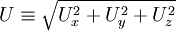
<math>U</math> can be computed from the three mean velocity components <math>U_x</math>, <math>U_y</math> and <math>U_z</math> as: | <math>U</math> can be computed from the three mean velocity components <math>U_x</math>, <math>U_y</math> and <math>U_z</math> as: | ||
| Line 19: | Line 19: | ||
When setting boundary conditions for a CFD simulation it is often necessary to estimate the turbulence intensity on the inlets. To do this accurately it is good to have some form of measurements or previous experince to base the estimate on. Here are a few examples of common estimations of the incoming turbulence intensity: | When setting boundary conditions for a CFD simulation it is often necessary to estimate the turbulence intensity on the inlets. To do this accurately it is good to have some form of measurements or previous experince to base the estimate on. Here are a few examples of common estimations of the incoming turbulence intensity: | ||
| - | #'''High-turbulence case''': High-speed flow inside complex geometries like heat-exchangers and flow inside rotating machinery (turbines and compressors). Typically | + | #'''High-turbulence case''': High-speed flow inside complex geometries like heat-exchangers and flow inside rotating machinery (turbines and compressors). Typically the turbulence intensity is between 5% and 20% |
| - | #'''Medium-turbulence case''': Flow in not-so-complex devices like large pipes, ventilation flows etc. or | + | #'''Medium-turbulence case''': Flow in not-so-complex devices like large pipes, ventilation flows etc. or low speed flows (low [[Reynolds number]]). Typically the turbulence intensity is between 1% and 5% |
| - | #'''Low-turbulence case''': Flow originating from a fluid that stands still, like | + | #'''Low-turbulence case''': Flow originating from a fluid that stands still, like external flow across cars, submarines and aircrafts. Very high-quality wind-tunnels can also reach really low turbulence levels. Typically the turbulence intensity is very low, well below 1%. |
| + | |||
| + | ===Fully developed pipe flow=== | ||
| + | |||
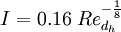
| + | For fully developed pipe flow the turbulence intensity at the core can be estimated as: | ||
| + | |||
| + | :<math>I = 0.16 \; Re_{d_h}^{-\frac{1}{8}}</math> | ||
| + | |||
| + | Where <math>Re_{d_h}</math> is the [[Reynolds number]] based on the pipe [[hydraulic diameter]] <math>d_h</math>. | ||
| + | |||
| + | The above equation is from the ANSYS Fluent User's Guide (Release 18.0, Eq. (6.62)); however, no reference is provided. Russo and Basse published a paper [1] where they derive turbulence intensity scaling laws based on CFD simulations and Princeton Superpipe measurements. The turbulence intensity over the pipe area is defined as an arithmetic mean (AM). The measurement-based scaling laws are: | ||
| + | |||
| + | :<math>I_{\rm Smooth~pipe~axis} = 0.0550 \; Re^{-0.0407}</math> | ||
| + | :<math>I_{\rm Smooth~pipe~area,~AM} = 0.227 \; Re^{-0.100}</math> | ||
| + | |||
| + | Scaling of the area-averaged (AA) turbulence intensity has been calculated in [2]: | ||
| + | |||
| + | :<math>I_{\rm Smooth~pipe~area,~AA} = 0.317 \; Re^{-0.110}</math> | ||
| + | |||
| + | == References == | ||
| + | |||
| + | {{reference-paper|author=[1] Russo, F. and Basse, N.T.|year=2016|title=Scaling of turbulence intensity for low-speed flow in smooth pipes|rest=Flow Meas. Instrum., vol. 52, pp. 101–114}} | ||
| + | |||
| + | {{reference-paper|author=[2] Basse, N.T.|year=2017|title=Turbulence intensity and the friction factor for smooth- and rough-wall pipe flow | ||
| + | |||
| + | |rest=Fluids, vol. 2, 30}} | ||
Revision as of 08:18, 11 June 2017
Contents |
Definition
The turbulence intensity, also often refered to as turbulence level, is defined as:

Where  is the root-mean-square of the turbulent velocity fluctuations and
  is the mean velocity (Reynolds averaged).
If the turbulent energy,  , is known can be computed as:
can be computed from the three mean velocity components  ,
,  and
and  as:
as:
Estimating the turbulence intensity
When setting boundary conditions for a CFD simulation it is often necessary to estimate the turbulence intensity on the inlets. To do this accurately it is good to have some form of measurements or previous experince to base the estimate on. Here are a few examples of common estimations of the incoming turbulence intensity:
- High-turbulence case: High-speed flow inside complex geometries like heat-exchangers and flow inside rotating machinery (turbines and compressors). Typically the turbulence intensity is between 5% and 20%
- Medium-turbulence case: Flow in not-so-complex devices like large pipes, ventilation flows etc. or low speed flows (low Reynolds number). Typically the turbulence intensity is between 1% and 5%
- Low-turbulence case: Flow originating from a fluid that stands still, like external flow across cars, submarines and aircrafts. Very high-quality wind-tunnels can also reach really low turbulence levels. Typically the turbulence intensity is very low, well below 1%.
Fully developed pipe flow
For fully developed pipe flow the turbulence intensity at the core can be estimated as:
Where  is the Reynolds number based on the pipe hydraulic diameter
  .
.
The above equation is from the ANSYS Fluent User's Guide (Release 18.0, Eq. (6.62)); however, no reference is provided. Russo and Basse published a paper [1] where they derive turbulence intensity scaling laws based on CFD simulations and Princeton Superpipe measurements. The turbulence intensity over the pipe area is defined as an arithmetic mean (AM). The measurement-based scaling laws are:


Scaling of the area-averaged (AA) turbulence intensity has been calculated in [2]:

References
[1] Russo, F. and Basse, N.T. (2016), "Scaling of turbulence intensity for low-speed flow in smooth pipes", Flow Meas. Instrum., vol. 52, pp. 101–114.
[2] Basse, N.T. (2017), "Turbulence intensity and the friction factor for smooth- and rough-wall pipe flow", Fluids, vol. 2, 30.