|
|
|
[Sponsors] | ||||
 March 12, 2013, 08:33
|
|
#1 |
|
New Member
Join Date: Mar 2013
Posts: 4
Rep Power: 13  |
Hi everyone!
I'm a beginner with Ansys / CFX and after completing a bunch of tutorials and doing some simple analyses, I am struggling now with the following problem: I want to simulate the rotation of the pistons of an axial piston pump (like this one). For simplicity, I broke down my problem to what you see in this picture:  The point is to simulate, how the rotating parts influence the fluid. The goal is to find out, how much drag force is created by the system. Until now, I fail to set up the system in CFX-Pre. I tried several things here: - Stationary fluid domain & rotating walls: This doesn't work, because the walls are not allowed to have normal velocity components - Rotating fluid & stationary / rotating walls: I tried around with some boundary conditions, but the results were always not as expected - Immersed solid (and a different mesh): This worked, but the results were quite incorrect. For example, I got result forces in X-Direction So, I'm lost here. Can anyone give me a hint on how to solve this? Or should I take a somewhat different approach? Last edited by donalffons; March 12, 2013 at 13:02. |
|

|

|
|
|
March 12, 2013, 12:59
|
|
#2 |
|
New Member
Join Date: Mar 2013
Posts: 4
Rep Power: 13 |
...for example: When I simulate the problem with a rotating fluid domain, the shaft and pistons as no-friction walls and the housing as a counter rotating wall, I get this as a result (velocity contour):
 ... which is not what I expect, of course. Since the fluid should move much faster near the center, where the rotating parts are. When I change the contour plot to velocity in Stn Frame it looks like this: 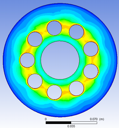 ...which kind of looks like what I am aiming for. I'm still not quite sure, if this is the right way to do such an analysis and if it actually captures what is happening physically. Can anyone tell me, if what I'm doing here is going into the right direction? |
|
|
|
|
|
|
March 12, 2013, 17:24
|
|
#3 |
|
Super Moderator
Glenn Horrocks
Join Date: Mar 2009
Location: Sydney, Australia
Posts: 17,703
Rep Power: 143 |
Have a look at the tutorials for the difference between velocity and vel in stn. frame.
Are you trying to simulation the region between the swash plate and the cylinder block? |
|
|
|
|
|
|
March 12, 2013, 17:42
|
|
#4 |
|
New Member
Join Date: Mar 2013
Posts: 4
Rep Power: 13 |
ghorrocks, yes, the area between the swash plate and the cylinder block.
I will do have a closer look at the tutorials tomorrow. Probably the multiphase mixing vessel could be a good start... I would appreciate any comments and advices on my case setup, since I'm totally not familiar with Ansys and CFD software in general. After the simulation, I want to extract the resulting drag moments with the torque_x@... functions. |
|
|
|
|
|
|
March 12, 2013, 18:11
|
|
#5 |
|
Super Moderator
Glenn Horrocks
Join Date: Mar 2009
Location: Sydney, Australia
Posts: 17,703
Rep Power: 143 |
The motion will be tricky. You might need to use moving mesh to model it. But, depending on what results you are looking for you might be able to simplify it to a frozen rotor model. That would be much easier, simpler and quicker - if it is appropriate.
Do the tutorial examples on moving mesh and rotating franes of reference to get a feel for these techniques. |
|
|
|
|
|
|
March 12, 2013, 18:36
|
|
#6 |
|
New Member
Join Date: Mar 2013
Posts: 4
Rep Power: 13 |
I played around with moving mesh simulations a few days ago, but I really had a hard time in getting the simulation to succeed (because of the negative volume error message). So I actually was hoping to avoid this kind of simulation...
I will investigate on the frozen rotor issue + rotating frames a little more. Thank you for your input! |
|
|
|
|
|
|
March 12, 2013, 18:40
|
|
#7 |
|
Super Moderator
Glenn Horrocks
Join Date: Mar 2009
Location: Sydney, Australia
Posts: 17,703
Rep Power: 143 |
Yes, movign mesh simulations are tricky to avoid folding the mesh. But that is going to be the most accurate way of modelling it.
|
|
|
|
|
|
 |
|
|
 Similar Threads
|
||||
| Thread | Thread Starter | Forum | Replies | Last Post |
| Simulation and Optimisation of centrifugal fan 3D to 2D | eRzBeNgEl | STAR-CCM+ | 0 | January 31, 2013 13:21 |
| errors in simulation with a rotating bowl | qq216 | OpenFOAM Running, Solving & CFD | 0 | January 26, 2013 11:30 |
| simulation results don't match with experimental results | funquest | CFX | 2 | January 19, 2013 20:24 |
| transient simulation of a rotating rectangle | icesniffer | CFX | 1 | August 8, 2009 07:25 |
| Rotating Arm Simulation | fluentnoob | FLUENT | 0 | June 23, 2009 10:56 |
 Linear Mode


