Fluent FAQ
From CFD-Wiki
(→FlowLab) |
|||
| Line 521: | Line 521: | ||
=== FlowLab === | === FlowLab === | ||
[http://flowlab.fluent.com] | [http://flowlab.fluent.com] | ||
| - | + | ||
| - | + | ||
[[Category: FAQ's]] | [[Category: FAQ's]] | ||
{{stub}} | {{stub}} | ||
Revision as of 12:13, 3 September 2011
This article contains questions and answers on the use of FLUENT products (mainly Fluent and Gambit). Please feel free to add questions and answers here!
General Information
What is Fluent?
There are two answers to this question: Fluent (the company) is a CFD software company that is now part of ANSYS Inc. Fluent (the software package) is a popular commercial CFD package.
What is Gambit?
Gambit is a meshing software package that is typically purchased with Fluent.
How can I learn Fluent and Gambit?
The documentation provided by Fluent is actually quite good, so it is a very good place to start. Fluent also provides tutorials and documentation on the fluentusers site, which is open to everyone with a (full) license. Without a full commercial license, it is possible to use the tutorials given at studentfluent, or you may be able to register to use the user services center through other channels (e.g. through the university program). There are also some good tutorials available at Cornell and at various other places on the web (Google is a good place to start).
Using CFD-Online's Fluent Forum
How should I ask my question on the Fluent forum to get the most useful answer?
It is important to understand that the quality of the answer to your question depends upon how well you ask your question. Many of the questions posted on the Fluent forum are so poorly posed that it is very difficult to understand what the poster is actually asking. Here are some suggestions to avoid this problem:
- Make sure your question is as clear, concise, and as specific as possible. Other forum readers are unlikely to spend time trying to decipher a garbled question.
- Give a clear general description of what class of problem and/or application you are working on before you start asking specific questions. This will aid other forum readers to better understand your specific questions.
- Describe precisely what you have done yourself to try and solve your problem, giving examples.
- Depending on your problem, you should try to include the following:
- If you are asking a mesh quality related question then include some sample images of your mesh, including the boundary layer.
- If you are asking a UDF question then include a copy of your existing code file as an attachment or in your post using <pre> tags to keep the code legible.
How do I upload images?
- Create the image on your local machine e.g. skew_mesh.jpg
- Upload the image to Imageshack
- Copy the link "Thumbnail for websites"
- Paste the link into your post e.g. <a href="http://img91.imageshack.us/my.php?image=pipeym8.jpg" target="_blank"><img src="http://img91.imageshack.us/img91/5681/pipeym8.th.jpg" border="0" alt="Free Image Hosting at www.ImageShack.us" /></a>
- If you have more than one file, zip them into a single file.
- Upload the file to Rapidshare Gigasize
- Scroll down to "I don't want a collector's account right now. Just give me the download-link." and click it.
- Scroll down until you see the link e.g. http://rapidshare.de/files/33808646/audio.log.html
FLUENT
Solver Related
What does "floating point error" mean? How can I avoid it?
The floating point error has been reported many times and discussed a lot. Here are some of the answers found in the Fluent Forum:
From numerical computation view point , the basic operations performed by computer are represented inside computer in what is called floating point numbers. The errors that are either because of invalid numeric computation initiated by user or limitation of machine that is used are floating point errors.
1)Invalid Operations:- Simplest example is if one uses Newton Raphson root finding method to solve f(x)=0 and for some Nth iteration if we get x = x(N) such that derivative of function f(x), f'(x(N))=0 then formula for calculating next iterate x(N+1) = x(N) - f(x(N))/f'(x(N)) requires division by f'(x(N)) which is zero. Here you get divide by zero type of floating point error.
2) Over or Underflow:- Another type is having data with either too large or too small magnitude called 'overflow' or 'underflow' respectively.Such data cannot be physically represented on computer for direct processing by arithmetic processing part of Processor.
3) Rounding off errors :- While rounding off a decimal number , some significant digits are lost which cannot be recovered . e.g. if we round off 0.1 to integer (not greater than it called 'floor' of the given no.) then it is zero. If this value if further used for computation then it may lead to several errors.
SOLVER AND ITERATION -----I think if you set shorter time step, it may be good. Or changing little Under-Relaxiation-Factors, it may be good. In my experience, I set 1/3 Under-Relaxiation-Factors as default.� -----�also lower the values of under relaxation factor and use the coupled implicit solver� -----�Try to change under-relaxation factors and if it is unsteady problem maybe time step is to large.� -----�you can improve the ratio in the solve--control--limits, maybe that can help.� -----�you will need to decrease the Courant number� -----�If you still get the error, initialize the domain with nothing to 'Compute from...' Then click 'init'. Again select the surface from which you want to compute the initial values & iterate. This should work.� -----�Another reason could be a to high courant number - that means, that the steps between two iterations are too large and the change in the results is too large as well (high residuals)�
GRID PROBLEMS -----�this error comes when I start scaling grid. in gambit, all my dimension is in mm, when in fluent i convert it in meter using buttone SCALE. after it, when i iterate, about hundred iteration, this error appeared. but when i not scale my drawing to m...and let it be as in gambit..then the iteration is success. -----�hi I think you should check your mesh grid mesh is very high. your problem solve by selection a low mesh.� -----�Your mesh is so heavy that your computers resources are not enough. try to use coarser mesh.�
BOUNDARY CONDITIONS -----�In my case I had set a wall boundary condition instead of an axis boundary condition and then FLuent refuses to calculate telling me 'floating point error'.� -----�Your Boudary Conditions do not represent real physis.� -----�wrong boundary condition definition might cause the floating point error. For example setting an internal boundary as interior� -----�Once I had the problem, simulating a 2D chamber with a symmetry BC. I set the symmetry somewhere as �axe symmetric� and the floating point error occur� -----�check the turbulence parameter you set. reduce the turbulence intensity to less that one for first, say 50 iterations.
MULTI PROCESSOR ISSUES -----"I've had similar problems recently with floating point errors on a multi processor simulation. The solution for my problem seems to be to run on a single processor, where it runs fine....?�
WRONG INITIATION ----- Initiating the case with wrong conditions may lead to floating point error when the iterations start.
What is the difference between the coupled and the segregated solver?
In the latest Fluent release,6.3.26 these are referred as density based and pressure based solvers.
The coupled solver will solve all equations (conservation equations for mass, momentum and energy) simultaneously instead of sequentially (the equations are segregated from one another). You should use the coupled solver when the velocity and pressure are strongly coupled (high pressures and high velocities), but very long calculation times may be required when you use the coupled solver.
In the coupled solvers, the Species Diffusion Term is always included in the energy equation.
When you use the segregated solver, FLUENT allows you to specify anisotropic conductivity for solid materials
From the Fluent forum:
Choice of solvers depends heavily on the model being solved. The segregated solver solution is based on the pressure, while the coupled solver solution is based on density. This makes the segregated solver better at low speed flows and the coupled solver better at solving transonic / supersonic cases. I wouldn't recommend the coupled solver at any flows below Mach .4 (until the pressure based coupled solver comes out in the next release of Fluent). I've used the Segregated solver up to Mach 1.5 with great results, but the higher speed, the more mesh dependent you become (because the segregated solver tends to "smooth out" shocks), so you have to pay a lot of attention to your meshing.
The coupled solver tends to be more stable with the defaults settings. The segregated solver tends to be very sensitive to the allowable limits. When trying to get a solution with the segregated solver, DO NOT increase the turbulent viscosity ratio limit (unless you have a great reason to based on past experience or the physics of your current model truly exceeding that limit, but I've never even heard of that being realistic). Instead limit the pressure and temperature limits to reasonable limits (i.e. Plimits = Pstatic +/- (2 * dynamic pressure), and calculate the appropriate temps). You need to give the solution "room to move" while it reaches a solution, but you don't want to give it enough room where it goes out to some totally impossible numbers, and the limits help prevent this.
Model Related
What is the turbulent viscosity ratio warning and how can I handle it?
The problem can be caused by improper values for the boundary condition turbulence parameters. Check the fluent manual (which is kind of more like a textbook), about modeling turbulence.
For the case of internal flow, you basically have to consider the physical state of the fluid upon entrance to your control volume. If the fluid is coming into your volume from a fully developed turbulent pipe flow, it will have more turbulent energy than from a stagnant fluid. Think of lots of little vortices, which mostly mix things up, and those all have kinetic energy associated). This energy can be expressed as a nondimensional Intensity (a percentage is used). In addition, a Length parameter is specified.
How can I determine the inputs for a porous media or porous jump from flow versus pressure drop data?
If you have pressure drop versus velocity data, you can fit the following equation through the data:
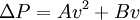
where  is the pressure drop and
  is the velocity. The coefficients
  and
and  are related to the Fluent variables for the permeability
  , and the pressure coefficient
  by
by
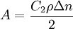 and
and 
where  is the thicknes of the medium.
How do I model heat conduction in a composite wall?
What pressures should be specified at inlets and outlets for buoyancy flow problems?
what pressures at inlet and outlet should specified in natural convection?
Are there any general guidelines on selecting a turbulence model?
How can both turbulent and laminar flow be included in one model?
Depends. Fluent cannot presently compute boundary layer instability and subsequent transition to turbulence using a RANS approach (ke, SST, RSM etc). CFX has a new feature to do this, so perhaps it will be incorporated into Fluent soon as they are both owned by ANSYS.
You therefore have two options :
1. If you know the point of transition (like on an aircraft wing) from experimental data or DNS simulations, you can impose laminar flow in some regions by meshing a separate fluid region, and enabling "laminar zone" for this region in boundary settings. That is also useful in heat transfer cases, if for example you have turbulent flow one side of a thermal wall, and natural convection on the other side.
2. A "near-wall" turbulence approach : Either k-omega, SST, or Low Reynolds k-E (which you have to select from the "Turbulence modelling/expert" menu), will damp turbulence near to the wall, either by empirical damping of turbulent "k" (Low Reynolds k-E) or by full solution of the omega equation on a fine enough mesh (k-omega/SST). If you have flows in small gaps in a larger, turbulent domain, in which large lengthscales of turbulence of course could not be supported, the flow will re-laminarise in a physically sensible (although perhaps not mathematically exact) manner. These models will also MAINTAIN laminar flow in external boundary layers, PROVIDED that you have a fine enough mesh (use the laminar mesh distribution guidelines in Fluent manual, too coarse a mesh will lead to non-physical turbulence generation in the BL). BUT they will maintain this laminar flow and evolution of the laminar profile (in the absence of significant disturbance by separation or impingement at the wall) forever, no spontaneous instability or transition to turbulence will occur. So check the length-based Reynolds numbers of walls where you think there will be undisturbed laminar boundaries, that there is not expected to be spontaneous transition of these BLs.
How to start a 3D simulation with an compressible medium and temperature changes? What is important to consider
I would do it that way:
1. solve the flow for incompressible medium, without energy equation. Set the density close to the density, that you expect at the present pressure and temperature. The solution for the flow dosn't has to be completely convergent, but the residuals should be on the way down.
2. Apply energy equation and compressibility of the gas and set the present pressure with operating condition option. You might do some iteration steps as well. Sometimes they are not necessary
3. Apply the thermal BC
Solution Methodology
How do I carry out rotating body analysis, eg a rotating sphere or cylinder in flow?
Rotating cylinder problem ( assume circular ), can be done easily by specifying angular velocity on the cylinder wall. As i observed no need of moving mesh for this case. you need to specify the rotation axis with respect to which your cylinder is rotating.
How do I get better and faster convergence?
What is the role of under-relaxation parameters? What should be the optimum choice of these parameters?
They limit the influence of the previous iteration over the present one. If you choose small values it may prevent oscillations in residuum developing. At the same time the solution may need more time to converge. Keep the default values as they are given in FLUENT. You can decrease them gradually if necessary. Momentum 0.6, pressure 0.1, k 0.4, eps 0.4, mass source 1, viscosity 1.
User-Defined Function (UDF) Related
How do I learn UDF programming?
There are not to many tutorials out there on this, probably due to the wide variety of things you can do with the UDF interface. The documentation the Fluent provides is pretty good once you know what you are trying to do (chapter 8 of the UDF manual has examples). UDF programming is easier if you have C programming experience, so it is advisable to learn a little C programming, then do some of the simple cases that Fluent provides, then tackle the problem you really want to solve.
How do I create/build/load a UDF?
The simplest way to add a UDF into Fluent is to write your UDF in the C programming language and then use Define -> User-Defined -> Functions to either interpret or compile your UDF. It can then be loaded. Fluent provides good documentation of the UDF interface with numerous examples, so read that before trying too much.
Do I have to use C?
Yes and no. To hook your UDF into Fluent, you'll probably have to use one of the DEFINE_* macros that Fluent provides, and this is most easily done using C. However, you can write routines that are used in the routines that are defined with the DEFINE_* macros in other languages and then link them together. This requires some knowledge of mixed language programming, Makefiles, the text user interface (TUI), and is not necessarily very portable. An example using Fortran is given in Section 5.4.1 of the Fluent UDF Manual (version 6.3).
Which compilers work?
On Unix-like machines, GCC is the compiler of choice. On Windows machines, Microsoft Visual C++ is the compiler of choice (GCC may also work on Windows- if anyone has firsthand knowledge of this, please share). The free Express Edition of the Microsoft compiler also works.
My UDF won't interpret or compile - what is wrong?
The answer depends upon what exactly has happened.
- If Fluent complains about not being able to find a compiler, then check to make sure that the compiler is properly installed. On Windows machines, it is possible to install the Visual C++ compiler without fully setting up the command line compiler (which Fluent needs to be able to find). During the installation process, you need to select the "register environment variables" option. Failure to do so will likely lead to complaints about things being "not recognized as an internal or external command, operable program or batch file" or missing DLL's. It is theoretically possible to fix this issue by setting the appropriate environment variables, but keep in mind that even when nmake can be found there still may be DLL issues. The easy path is probably reinstallation of Visual Studio (taking special care to make sure that the command line interface is set up properly), but the reinstallation path is always perilous. If you have long-term experience using Windows you should probably know the risks, and if you don't you should consult an expert.
- If you are interpreting, keep in mind that not everything that is supported for compiled UDF's is supported for interpreted UDF's. This is true both for the UDF interface and the C language. If you are doing something pretty involved and it fails inexplicably, try compiling to see if that makes a difference.
- There is also the possibility of coding errors. Keep in mind that your source code gets run through the C preprocessor (to change the Fluent macros into C code), so unintended interactions are very possible.
Why do I get the message "'nmake' is not recognized as an internal or external command, operable program or batch file"?
This is a Windows/Visual Studio issue. In order to compile your UDF, Fluent needs to know where the nmake program is located, and it currently can't find it. If you open up a command window and enter "nmake", you should probably get the same message. See the previous question/answer.
My UDF interprets/compiles but fails to execute - what is wrong?
This commonly occurs due to a faulty operation of some kind. For example, user-defined memory (UDM) is not allocated until initialization, so attempting to access a UDM variable before initialization can lead to a segmentation fault. Try to isolate the cause, and then look for places where your expectation of what is available may not match reality. Finally, keep in mind that if you do something really bad, you may need to restart Fluent before even a fixed UDF will work.
How-To Setup Microsoft Visual C++ 10.0 to Work with Fluent 13
In the Fluent Launcher, there is a tab called "Environment". On this tab there is a check box "Setup Compilation Environment for UDF", which has to be checked. If this is not enough, and the compilation still fails, then the udf.bat file should be edited. The following has to be added
- set MSVC_DEFAULT=%ProgramFiles%\Microsoft Visual Studio 10.0
- if exist "%MSVC_DEFAULT%\vC\vcvarsall.bat" set MSVC=%MSVC_DEFAULT%
- if not "%MSVC%" == "" goto msvc_env10
- msvc_env10
- set MSVC_VERSION=10
- call "%MSVC%\VC\vcvarsall.bat" x86
- goto msvc_end
Basically it tries to run the vcvarsall.bat script. That is it!
How-To on most Windows 32bit systems
The questions surfacing in the discussion forum are most of the time solved with some simple steps.
As they are mentioned frequently it may be appropriate to mention the solution steps here:
- Install Visual Studio. Most of the time the Visual C++ 2008 Express Edition [1] is recommended. On my system it even works with the new Visual Studio 2010 Professional Release Candidate [2].
- Set the correct environment variables. Browse your way through the Windows system control to 'System'. There you will find a section 'Advanced system settings'. In the following dialog go to the 'Advanced' tabulator and click on 'Environment variables' (lower right corner). Go through the 'System variables' list and search for the 'Path' entry. Add the following to the variable: C:\Program Files (x86)\Microsoft Visual Studio 10.0\Common7\Tools;C:\Program Files (x86)\Microsoft Visual Studio 10.0\VC\bin;C:\Program Files\ANSYS Inc\v120\fluent\ntbin\win64. Adjust this entry to your system concerning the installation directories!
- The Visual Studio entry should point to the location where 'nmake.exe' is located. If this file is missing while trying to compile your UDF you will be fine with this step. If other files are missing during the compilation find their location on you hard disc and add their directory to the PATH entry.
- Run FLUENT from the Visual Studio command prompt! This is what most of the users don't know. Start the Visual Studio command prompt which comes with your Visual Studio installation. It is the familiar Windows style command prompt. Navigate to the directory, where your FLUENT files are and start FLUENT by entering 'fluent'. Don't use symbols on your desktop or start menue entries to start FLUENT. (This does not apply to 64bit systems! See this entry.)
How can I manage to compile my UDF with Windows 7 64bit?
This problem sometimes looks similar to the one concerning the missing 'nmake'.
- Install Visual Studio. Most of the time the Visual C++ 2008 Express Edition [3] is recommended. On my system it even works with the new Visual Studio 2010 Professional Release Candidate [4].
- Set the correct environment variables. Browse your way through the Windows system control to 'System'. There you will find a section 'Advanced system settings'. In the following dialog go to the 'Advanced' tabulator and click on 'Environment variables' (lower right corner). Go through the 'System variables' list and search for the 'Path' entry. Add the following to the variable: C:\Program Files (x86)\Microsoft Visual Studio 10.0\Common7\Tools;C:\Program Files (x86)\Microsoft Visual Studio 10.0\VC\bin;C:\Program Files\ANSYS Inc\v120\fluent\ntbin\win64. Adjust this entry to your system concerning the installation directories! The Visual Studio entry should point to the location where 'nmake' is located.
- Install a Software Development Kit (SKD) for 64bit systems. This may be the difference between 32bit and 64bit systems. I have used the .NET Framework 2.0 Software Development Kit (SDK) (x64) from 2006 [5] because it is explicitly for 64bit systems and I was not sure if more recent versions are for 64bit systems as well.
- Start FLUENT from the SDK command prompt. Do not use the Visual Studio command prompt, use the SDK command prompt! Go to the directory your case is in and type 'fluent'.
Post-Processing Related
What is the best way to generate an animation?
There are several ways to do this (both inside and outside of Fluent), and all have merits, so there is probably no "best" way. There are two approaches to using Fluent to generate the graphics: use Fluent to generate the movie (using Solve->Animate->Define...) or use Fluent to generate individual frames of an animation (by generating a hardcopy image at appropriate intervals, then assemble the animation with an external program. Many available postprocessing tools (e.g. Tecplot) can also generate animations, so saving complete data files for use with the postprocessor can also be a path to a animation.
What hardcopy format should I use?
The answer here depends upon what you need. For maximum accuracy, use a lossless format (e.g. PPM). The disadvantage of the lossless formats is usually the size of the files. For smaller file size, use a format like JPEG, which will lose some detail. In some cases, the loss of detail will not be be easy to see, while it may be in others.
Journal File and Text User Interface (TUI) Related
What is the Text User Interface?
The Text User Interface (TUI) is a command-line-like interface to Fluent. The TUI is accessed through the main Fluent (hit enter while in the main Fluent window), with a menu system and the ability to execute Scheme programs. Fluent's documentation compares the menu system to the UNIX directory structure. Since it is text base, you can create and modify sequences of TUI commands using a simple text editor (see journal files below).
When Fluent starts, you are in the "root" menu: press enter and you'll see something like this:
>
adapt/                  file/                   report/
define/                 grid/                   solve/
display/                parallel/               surface/
exit                    plot/                   view/
To access the plot menu, just type in "plot" and then press enter. To bring up the available commands, press enter again:
> plot

/plot>
change-fft-ref-pressure file-set/               residuals
circum-avg-axial        flamelet-curves         residuals-set/
circum-avg-radial       histogram               solution
fft                     histogram-set/          solution-set/
file                    plot
file-list               plot-direction
To exit a menu, simply type "q" and press enter (the rough equivalent of "cd .." in Unix). The TUI also understands command abreviations, so "pl/rs" is interpreted as "plot/residuals-set".
What is a journal file?
A journal file is a series of TUI commands stored in a text file. The file can be written in a text editor or generated by Fluent as a transcript of the commands given to Fluent during your session. A journal file generated by Fluent will include any GUI operations (in a TUI form, though). This is quite useful if you have a series of tasks that you need to execute, as it provides a shortcut. To record a journal file, start recording with File -> Write -> Start Journal..., perform whatever tasks you need, and then stop recording with File -> Write -> Stop Journal...
How do I add a comment in a journal file?
Any line beginning with a ; (semicolon) is treated as a comment.
How do I set boundary conditions?
Suppose we have a boundary named "south" that we want to set as a wall. The command is
/define/boundary-conditions/zone-type south wall
which sets the zone "south" as a wall. The details (moving wall, etc.) can then be accessed be executing
/define/boundary-conditions/wall south
in the text user interface.
How do I write a XY-plot?
look at http://www.cfd-online.com/Forum/fluent_archive.cgi?read=40200
How do I set material properties?
look at http://www.cfd-online.com/Forum/fluent_archive.cgi?read=38768
one example:
//define/materials/delete
air_50c
//define/materials/delete
air_1bar
//define/materials/change-create
air
air_1bar
y
incompressible-ideal-gas
y
piecewise-linear
2
298.15
1007
323.15
1008
y
piecewise-linear
2
298.15
0.02606
323.15
0.02788
y
piecewise-linear
2
273.15
1.72E-05
433.15
2.45E-05
n
n
n
n
n
n
y
How do I generate a hardcopy of a window?
display set-window 1                    ; if window nr. 1 is the window you want to be hardcopied
//display/set/windows/scale/form        ; setting the options for the graph (colourmap)
"%0.2f"
//display/set/color-ramp
bgr
//display/set/hardcopy/color            ; setting the options for the window<
color
//display/set/hardcopy/driver
tiff
//display/set/hardcopy/y-res
2400
//display/set/hardcopy/x-res
3106
//display/set/hardcopy/inv
no
//display/hard
filename.tiff
//display/set/hardcopy/inv
yes
//display/hard
filename_inv.tiff
How do I run multiple cases in batch mode?
This could be achieved by running it from journal file. The example journal file that runs two cases is given as:
file read-case-data xxx1.cas
solve dual-time-iterate yyy1
file write-case-data zzz1.cas
file read-case-data xxx2.cas
yes                                            ; for discard cas dialog
solve dual-time-iterate yyy2
file write-case-data zzz2.cas
Another example:
rcd filemname.cas
yes
it 10000
wcd filemname.cas
yes
Have a look at this discussion: http://www.cfd-online.com/Forum/fluent_archive_2005.cgi/read/32615
How do I loop in a journal file?
The best way to loop in a journal file (or the text user interface) is to use one of the Scheme programming language's looping constructs.
What are the available scheme functions in fluent's environment?
There isn't too much documentation related to fluent and its own implemented scheme language. Here it comes a document written in german that explains some of the variables and functions: ["Fluent Scheme - Mirko J."]. An english version of it can be found at: ["English Translation"].
A list of fluent variables and functions with some comments and examples is provided here:
Any contribution to this list is welcome.
How do I debug a fluent udf using gdb
- Udf_debug - a short debugging session of a fluent udf using gdb.
Tips
How do I merge two mesh files into one mesh file?
To merge two mesh files the suggested utility is tmerge. The syntax of tmerge is simple.
utility tmerge -3d file1 file2 finalfile
To join the two interior faces use:
Grid->Fuse
from the menu with Fluent.
How do I export Fieldview data for postprocessing during iterations?
This could be done with the help of menu solve->Execute Commands . Here are two examples:
Steady Case
file/export/fug/File_grid-%n
file/export/fud/File_data-%n pressure velocity-magnitude x-velocity y-velocity z-velocity ()
Unsteady Case
file/export/fug/File_grid-%t
file/export/fud/File_data-%t pressure velocity-magnitude x-velocity y-velocity z-velocity ()
You can chose the frequency of export from the Execute Command panel.
What does abbreviation X mean?
| APG | adverse pressure gradient |
| BC | Boundary Conditions |
| B-L | Boundary Layer |
| CFD | Computational Fluid Dynamics |
| DES | Detached Eddy Simulation |
| DPM | Discrete Phase Model |
| FDM | Finite Difference Method |
| FEM | Finite Element Method |
| FVM | Finite Volume Method |
| FDS | Flux Difference Splitting |
| FVS | Flux Vector Splitting |
| AUSM | Advection Upstream Splitting Method |
| GUI | Graphical User Interface |
| LES | Large Eddy Simulation |
| MUSCL | Monotone Upstream-centered Scheme for Conservation Laws |
| MDM | Moving and Deforming Mesh |
| Probability Density Function | |
| QUICK | Quadratic Upstream Interpolation for Convective Kinematics |
| RANS | Reynolds Averaged Navier-Stokes |
| RSM | Reynolds Stress Model |
| SIMPLE | Semi-Implicit Method for the Pressure-Linked Equation |
| SST | Shear Stress Transport |
| TUI | Text User Interface |
| UDF | User defined function |
| URF | Under Relaxation Factor |
| VOF | Volume Of Fluid |
What is the difference between FE and FV?
See the answer in the General CFD FAQ.
FloWizard
FIDAP
POLYFLOW
Gambit
Why does Gambit refuse to open my .dbs file and say that my file is already open? I get an error message - ERROR: IDENTIFIER "X" CURRENTLY OPEN.
Before opening your file "X.dbs", Gambit looks for a file named "X.lok" to determine the status of your file. If it finds the .lok file, you'll get the above error message (or something like it). If you are in a multi-user environment, you should check that it is not actually already open elsewhere, but in other situations the most likely reason that there is still a X.lok file is that Gambit encountered a problem the last time X.dbs was open. Deleting the .lok file should solve your problem.
Q: Why does Gambit complain about the number of nodes on edges being odd and then refuse to mesh a face?
A: It is mathematically impossible to create an all-quad mesh with an odd number of intervals on the outer edge loop. If this is inconvenient for you, you may consider a quad-dominant mesh (mostly quads, with a few triangles), or even an all-triangle mesh. Many users achieved good solutions with triangle surface meshes and prism (wedge) boundary layers.
Q: What are these boundary layers things defined in Gambit? Do they represent the real situation?
A: Gambit's boundary layers allow you to generate specific semi-structured grids topologies on faces that grow out from an edge or edges. You can specify the initial cell height, the growth rate, and a transition pattern that changes the edge-parallel interval count. There are several default settings, which can affect the quality of boundary layers. For cases with sharp corners, normal and offset smoothing can greatly improve quality. Such smoothing is off by default because it requires significantly more computation time.
Q: If my quad face mesh has cells with high skewness or large aspect ratios, the pyramiding procedure used by the tet mesher will frequently lead to failure, why?
A: This is because the triangles on the tops of the pyramids have very high skewnesses which can prevent tet meshing. Consider a quad face with a 10-to-1 aspect ratio. Connect opposite corners to create diagonals. This is the "top view" of the pyramid that would be created on this face. The triangles are very highly skewed. It is recommended that your quad faces bounding a region to be tet-meshed have aspect ratios of 5-to-1 or lower.
Q: I'm trying to mesh a geometry but I'm getting this message: “check the skewnesses of you face meshes and make sure the face mesh sizes are not too large in areas of small gaps.” I checked the skewness and it's low enough.
A: Your problem is most likely that you have small gaps where the local surface mesh sizes are much larger than the gap sizes. Refining the surface meshes in those areas is likely to solve the problem.
Q: I would like to generate grids for different zones using Gambit. How do I merge them together using Gambit or Tgrid later?
A: For a valid conformal mesh, mesh nodes on the faces at the interface of the two parts have to be matching within a tolerance. Then, you can either merge the nodes (using Tgrid) or fuse the zones (using Fluent). If you use Tgrid to merge the duplicate nodes, the resulting surface at the interface will have the boundary type as "wall" which should be changed to "interior" if both sides of the interface have same cell (fluid) zone. Fluent automatically converts the resulting surface after fuse to be of "interior" type if both sides of it has the same cell (fluid) zone.
Also, if you are not using Tgrid, you need to use tfilter tmerge3d to merge the meshes together before reading them into Fluent. Tgrid does the same when you load multiple mesh files at a time.
Q: How do I determine what kind of grid to generate? (I would like to known selection criteria between structured and unstructured mesh.)
A: Try this approach - consider the meshing options in this order: Single-Block Structured, Multi-Block Structured, Multi-Block Hybrid/Mixed, Fully Unstructured. Gambit can generate most of the cells types and topologies that Fluent can use (with the notable exception of nonconformal meshes). Here are some guidelines/suggestions:
- If you can generate a single-block structured mesh for your problem, then stop there. There is no need to go further.
- If your solution is having problem around a corner (or the like), try multi-block structured mesh. If you are getting improved solution, then stop there.
- If you still have problems around different part of the corner, try the unstructured mesh, with high density mesh around the corner. Before going to a fully unstructured mesh, try making only the problem region unstructured. If the solution is good, then stop there.
- If one part of the mesh still requires special attention, then you can use Fluent's adaptive unstructured facility to refine the mesh until the solution is acceptable. Ideally, you should still get a mesh independent solution.
- It is very important to be able to control every part of your mesh so that you can get good solution everywhere. This is more difficult with unstructured meshes.
- For many geometries, if you can use a structured mesh you will end up with fewer cells (this is particularly true in three dimensions). It is a good idea to use structured-type meshes in regions that will allow it, and use unstructured meshes everywhere else.
- Don't forget that Fluent can handle prismatic cells. If you have an unstructured surface mesh, Gambit can generate a layer of prismatic cells that will resolve boundary layers without requiring a (fully) structured mesh.
Q: How do I run GAMBIT as a batch process?
A: To run Gambit in "batch" mode, prepare a journal file (e.g., "test.jou"), then use the command : gambit test -in test.jou
Q: I am having trouble uniting two volumes, what should I do?
"misclassified graph coedge - probably geometrical problem"
-> you can try healing the volumes
-> deleting the volume (without lower geometry), healing and uniting the faces, then build the volume again
Q: I am trying to move a node to modify the mesh on a face with mouse. Why in y direction I can only move the node discretely by 0.5 or multiples of 0.5? I can move it continuously in x direction and I would like to do so in y as well. Is there some default value to change?
Other Preprocessing Codes
Gambit Turbo
TGrid
Application specific codes
Icepak
Airpak
MixSim
Educational codes
FlowLab