Hydraulic diameter
From CFD-Wiki
The hydraulic diameter,  , is commonly used when dealing with non-circular pipes, holes or ducts.
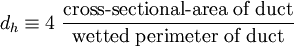
The definition of the hydraulic diamater is:
Contents |
Use of hydraulic diameter
Estimating the turbulent length-scale
For fully-developed flow in non-circular ducts the turbulent length scale can be estimated as  . This is as usefull estimation for setting turbulence boundary conditions for inlets that have fully developed flow.
Computing Reynolds number
The hydraulic diamater is often used when computing the dimensionless Reynolds number for non-circular ducts.
Hydraulic diameters for different duct-geometries
Using the definition above the hydraulic diamater can easily be computed for any type of duct-geometry. Below follows a few examples.
Circular pipe
For a circular pipe or hole the hydraulic diamater is:
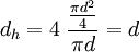
Where d is the real diameter of the pipe. Hence, for circular pipes the hydraulic diameter is the same as the real diameter of the pipe.
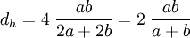
Rectangular tube
For a rectangular tube or hole with the width  and the height
  the hydraulic diamter is:
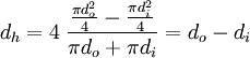
Coaxial circular tube
For a coaxial circular tube with an inner diameter  and an outer diameter
  the hydraulic diameter is: