|
|
|
[Sponsors] | ||||
[ICEM] How can I fill curve body with 3D hexa mesh? |
 |
|
|
LinkBack | Thread Tools | Search this Thread | Display Modes |
 October 5, 2016, 18:56
|
|
#1 |
|
New Member
Join Date: Oct 2015
Posts: 24
Rep Power: 10  |
Hello all,
First I want to point out which I do not understand logic about filling curve with linear lines. In this photo, gaps formation is clear.  Gap size is going to decrease if I increase the node number like this,  But the problem is there is no way to fill all gaps because we have to have infinite number of linear lines to make curvature. My question is how can I make this possible in ICEM-CFD like sweep mesh in ANSYS Workbench Mesher? |
|

|

|
|
|
October 6, 2016, 05:05
|
|
#2 |
|
Senior Member
Sebastian Engel
Join Date: Jun 2011
Location: Germany
Posts: 566
Rep Power: 20 |
Hi Kosmosisy,
about logic about filling curve with linear lines: Well, cfd uses volume elements with linear boundaries. Hence, a non-linear curve cannot be perfectly represented by linear elements. I would consider this a discretization error which is not avoidable, we can only reduce it by e.g. taking more elements. You might wonder, why the in the first picture last three edges on the right side doesn't follow the curve as well as the left part. Well, have a detailed look on your blocking. There is a central block within your half cylinder. A single block where three faces extendes to the surrounding "collar". These collar blocks therefore have dependent number of elements to the central block. If you only have 4 nodes on the short edge of the central block the collar blocks to the left and right also only have 4 nodes in that direction. Hence, it might be neccessary to increase the number of nodes on this edge even if you don't need as many elements in the central block. Your conclusion that you would need infinite number of elements to fill all gaps with linear elements is absolutely right. If you want to do CFD, ..., non-linear elements simulation are not common. So creating non-linear elements would be pointless. For other FEA sims have a look in this thread http://www.cfd-online.com/Forums/ans...atic-hexa.html Convert your premesh to unstructured mesh and test the convert mesh features. i haven't tried them myself, though. Ok, number of elements and non-linear elements are ways to improve discretization. Another lever is distribution of elements, as you probably know! Well if you haven't changed the standard settings, then ICEM distributes vertices uniform on a given edge. This uniform distribution is independent from curves. So.. it's another source for the large gaps in your geometry to the curves. However, there is a so-called "mesh law" to distribute the nodes which will help you. Search for "curvature" mesh law in the edge params. This will try to optimize the vertices distribution to reduce curvature discretization error. with regards, Sebastian |
|
|
|
|
|
|
October 6, 2016, 05:53
|
|
#3 | |
|
New Member
Join Date: Oct 2015
Posts: 24
Rep Power: 10 |
Quote:
Thank you for your reply. I have much more better understanding now. May I ask another question? It is again about gaps. This block is inside flow channel. 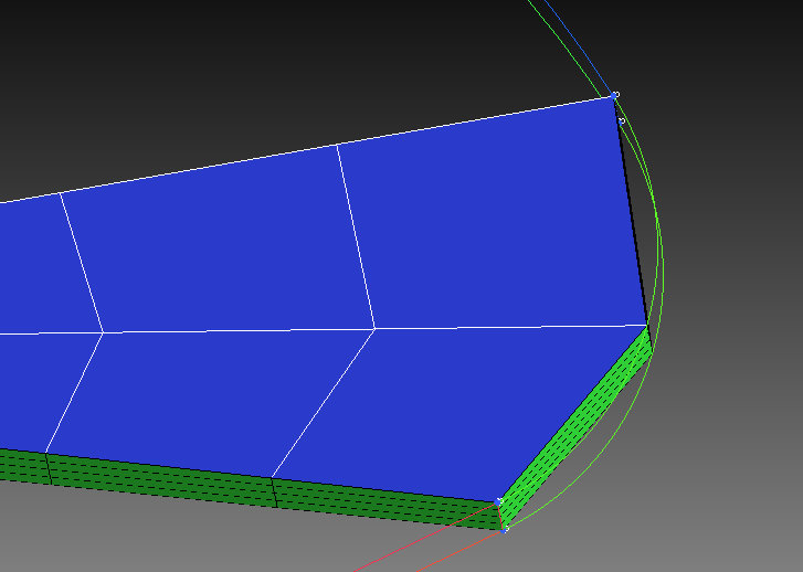 By the way this geometry is anode plate of fuel cell, plate is carved to form flow channels. If I merge verticies of two blocks, gaps will be no longer exist. However, the problem is some cells exist in both fluid and solid region. The second block(right one) is inside solid region but shaded areas are inside the fluid region.  Again will it cause the discretization error? If yes, I can lower it with increasing nodes and curvature mesh law like you have already mentioned or ICEM or FLUENT somehow deal with it since I have defined the associations? Yours Sincerely, Şanser |
||
|
|
|
||
|
October 6, 2016, 08:15
|
|
#4 |
|
Senior Member
Sebastian Engel
Join Date: Jun 2011
Location: Germany
Posts: 566
Rep Power: 20 |
Hi Şanser,
I don't want to make this sound like lecture. Though, i have the impression there is a concept which haven't become second nature to you yet. in mathematical point of view you will always have an (geometric) discretization error when trying to discretize a non-linear curve by linear elements. Usually, it can't be avoided. We only can minimize discretization error by using more elements. For that reason we usually have a hugh number of elements in FEA simulations nowadays. It feels somewhat logical to me, that a model/simulation is simpler than reality. And simpler means errornous. We accept these errors if they are relatively small to the amount of work we put into a simulation. I believe that you can answer your question yourself already. "Is there a discr. error in both volumes - solid and fluid - by my current mesh?" Yes, definitely! For both volumes the curve is represented by only two elements. So both volumes representations exhibit some errors in this region. Though, the combined discretization error might by smaller in your case. The reason for that is that both volumes have a matching interface. However, the graveness of this error needs to be determined by yourself. Does an edge geometry representation changes the usefullness of the simulation's result? Or with different words: Would a finer mesh improve the plausibility/reduce the error to reality of your simulation, and would the increased cost of a finer simulation be justified? --- Without knowing many details on your simulation and without having any knowledge on fuel cell simulations i just would suggest you to refine your mesh significantly. It seems you don't have many cells in the first place. The increased cost therefore seem to be negletable. "Associations" are a concept of ICEM to create the premesh. This property is not passed onto the exported mesh (afaik). For that reason, fluent (or other solvers) won't know anything about the curve of the geometry in ICEM. So... No, neither ICEM nor fluent will somehow deal with that problem of those gaps. You will have to deal with that problem manually (by increasing node number, improving distribution, ...) With regards, Sebastian |
|
|
|
|
|
|
October 16, 2018, 10:54
|
|
#5 |
|
Member
MWRS
Join Date: Apr 2018
Location: Islamabad
Posts: 99
Rep Power: 8 |
How do I fix this curvature issue for Tetra mesh in ICEM?
|
|
|
|
|
|
|
|
|
 Similar Threads
|
||||
| Thread | Thread Starter | Forum | Replies | Last Post |
| [mesh manipulation] Importing Multiple Meshes | thomasnwalshiii | OpenFOAM Meshing & Mesh Conversion | 18 | December 19, 2015 18:57 |
| [ICEM] Hybrid mesh hexa and tetra on ICEM | PeterDaniel | ANSYS Meshing & Geometry | 0 | October 22, 2013 12:22 |
| 3D Hybrid Mesh Errors | DarrenC | ANSYS Meshing & Geometry | 11 | August 5, 2013 06:42 |
| [ICEM] Problem making structured mesh on a surface | froztbear | ANSYS Meshing & Geometry | 4 | November 10, 2011 08:52 |
| [ICEM] Problem making structural mesh on a surface | froztbear | ANSYS Meshing & Geometry | 1 | November 10, 2011 08:52 |
 3Likes

 Linear Mode


