 |
|
|
[Sponsors] | |||||
|
|
|
#1 |
|
Member
Join Date: Sep 2009
Posts: 69
Rep Power: 16  |
Hi everyone,
I am currently working on a 3D Hybrid mesh of an extruded NACA0012 airfoil. Basically I want to make the mesh just beside the airfoil structured for a certain distance and the rest of the farfield unstructured. While I am very close to getting it error-free, I have a few niggling ones that would not go away no matter what I tried. The following pic is my geometry and a close-up of the airfoil with the blocking. 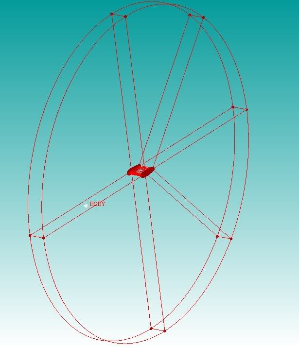 Farfield geometry with Airfoil in the middle. Surfaces ommited to reduce clutter. Basically to make this geometry, I define all the points of the airfoil and farfield and connected the points in a plane/surface. Then I use transform geometry to make a copy of those points/curves at an offset. I then connected both these planar geometries using curves so that i can start creating surfaces on them. I grouped these surfaces into different parts : AIRFOIL - 'Airfoil surface' AIRFOIL2 - ' Interface wall between the structured and unstructured mesh' BLAYER & BLAYER1 - ' Side walls that connect Airfoil and Airfoil2 at the sides of the mesh. Basically covering the ends of the structured mesh section' FARFIELD & FARFIELD1 -' Similar to Blayer walls but covering the sides of the unstructured mesh section' EXTRUDE - 'Cyllindrical ring that connects both farfield and farfield1 at its outer edges'. 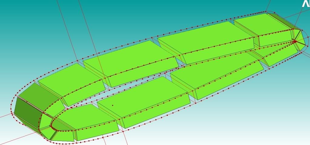 Airfoil geometry closeup with blocking to show required structured part of mesh. Then I proceeded to do the blocking as shown above. After the blocking I followed the method as described by the hybrid tube tutorial : 1. Create body in unstructured area. 2. Part mesh size, set sizes for AIRFOIL2, FARFIELD, FARFIELD1 and EXTRUDE 3.Volume Mesh - Compute Once the unstructured mesh is computed, I turn it off on the tree and proceed to setup the pre-mesh params of the blocks, setting it up so that the hex elements on the AIRFOIL2 surface is about the same size as the TRI that just got meshed on that surface. Once that is done i save the blocking, and load mesh from blocking. Mesh Exist - I click Merge. Then I go to edit mesh > merge nodes > merge mesh. Under merge surface mesh parts, I choose AIRFOIL2..........and this is where things get interesting. First off I get a heap of errors. unable to remove prism node 33727 unable to remove prism node 34259 unable to remove prism node 41365 i get a lot of this, then potential problem: 97 orphans could not be removed error including edge 330839 330909 error including edge 6929212 6929216 error including edge 7116935 7116937 error including edge 7116935 7116937 could not include quad unable to include quad 244670 (6489089 6499659 6499589 6489159) unable to include quad 244819 (6499589 6510159 6510089 6499659) these are just a few examples, but i get them repeatedly. Then I Run check mesh, with all the default checks and the 1st one I got was volume orientations, shown below 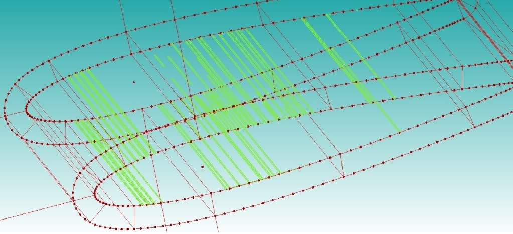 These are basically happening at the wall of the airfoil where the first layer of the structured mesh begins, and I sort of know what is happening here. My boundary layer mesh is too thin (first layer 0.001) and somehow the geometry dosent like it. Ive tried to use Build Topology but that only reduced it in numbers but did not eliminate it. Besides I try to refrain from using it as it occasionally messes up my geometry. What else can I do to eliminate the problem. Ive tried to increase the chordwise elements but that did not help. Next problem, I have multiple edges on the geometry as shown with a little section of non-manifold vertices (colored in blue): 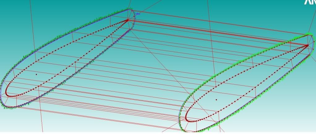 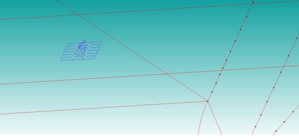 Close up of non manifold vertices My intuition tells me that multiple edges at that section is correct and can be ignored. But I am not sure what this non manifold vertice is. Anyone knows how to get rid of this problem? It seems to me that the TRI elements are penetrating the quad elements in this section as the pyramid was not created there. How it is possible to rid of this problem? Ive tried to build different geometries to get rid of the problem but it always surfaces in different parts of the mesh, most notably at the edges. Hope someone can shed some light into the problems that I am having. I have tried numerous things, rebuild geometries, building topologies, mesh refinement , blocking strategies etc etc but to no avail. I always get those error messages and mesh check errors in one form or another. Fingers crossed that this will be one long and knowledgeable thread =) THANKS!!!! Regards, Darren |
|
|
|

|
|
|
|
|
#2 |
|
Member
Join Date: Sep 2009
Posts: 69
Rep Power: 16  |
I actually forgot to include one important bit of information. I use ICEM for my mesh

|
|
|
|

|
|
|
|
|
#3 |
|
Member
Join Date: Sep 2009
Posts: 69
Rep Power: 16  |
Hi guys,
I have managed to solve some of the problem and I thought I should share it with you all. First of all the penetrating elements/non manifold vertices problem. The problem for me was that the hex elements on the interface between structured/unstructured interface was not square enough. The mesher would prefer a hex element with ideally equilateral sides and so i just adjusted the pre mesh params and viola!. Also you will get this problem if the size of your hex and triangles on the interface mesh has too big of a size difference. Try to make them as equal as possible in terms of size. One problem that I am still not able to fix is the Volume Orientations problem. Ive worked on this problem forever and it still wouldn't go away. Can someone please help me!! I am about to put a hole into my monitor!! Simon where are you?? =) Darren |
|
|
|

|
|
|
|
|
#4 |
|
Senior Member
Simon Pereira
Join Date: Mar 2009
Location: Ann Arbor, MI
Posts: 2,663
Blog Entries: 1
Rep Power: 47   |
Hey Sorry Darren,
A bunch of my CFD-Online emails got shunted off and I never saw this until today. If you still need help, I can help... Or take a quick look at the movie(s) I put on the YouTube Site (www.youtube.com/ansysinc/) I would suggest that a pure hex mesh would be better, or since it is a swept geometry, how about quads in your boundary layer region and tri's elsewhere and then sweep them into prisms and hexas? Simon |
|
|
|

|
|
|
|
|
#5 |
|
New Member
Qiulan Zeng
Join Date: Sep 2010
Posts: 18
Rep Power: 15  |
Dear Simon,
I couldn't find the vedio. Could you send it to me? My email is 'qiulan.zeng@gmail.com' .Thank you very much!! 
|
|
|
|

|
|
|
|
|
#6 |
|
Senior Member
Simon Pereira
Join Date: Mar 2009
Location: Ann Arbor, MI
Posts: 2,663
Blog Entries: 1
Rep Power: 47   |
Now you need to insert the word user...
http://www.youtube.com/user/ansysinc And this is the link to the first of the three vids... Hopefully, you will be able to browse to the second from here... http://www.youtube.com/user/ansysinc#p/u/8/tYrbScUH9RE Simon |
|
|
|

|
|
|
|
|
#7 |
|
New Member
Qiulan Zeng
Join Date: Sep 2010
Posts: 18
Rep Power: 15  |
Dear Simon,
Thank you very much! I can browse to the two links you've sent to me. But it seems they are not examples of using hybrid meshing, are they? I have not found the vidio I need.... These days I have encoutered some problems about 3D hybrid meshing which I sent to you in another post reply. http://www.cfd-online.com/Forums/ans...tml#post281515 Iíve tried numerous times but failed everytime.  I desperately need your help and am anxious to hear from you. I desperately need your help and am anxious to hear from you.Thank you very much! Qiulan |
|
|
|

|
|
|
|
|
#8 |
|
New Member
Join Date: May 2013
Posts: 7
Rep Power: 13  |
Hi every one
I want to ask a question about hybrid mesh in icem cfd I want to mesh a complex case with hybrid mesh and for that I use hybrid mesh for simple case to know it procedure well and then do the complex case. I search in the forum and read the most topics that simon ,far,dimondix ,Ö.. explained on how is the procedure of the hybrid mesh in 3d case. I have also read the tutorial of 2d hybrid mesh that far put in the forum and learned a lot in 2d case. But in 3d case I have a problem now although I read the most topics of hybrid mesh. In my simple case I want to mesh a wing. I split the domain into uns(tetra) and str(hexa) with the surface that I named it interface and know that it must be the separate part. At first I mesh the uns domain then save the mesh uns. Then blocking the wing and save the blocking then load the mesh from blocking.select merge .now I have two domain with tetra and hexa mesh. then go to merge surface mesh part and select interface. But I receive some error in merge procedure like : 528 shells from the variable region deleted 260 bars from the variable region deleted unable to remove prism node 8 9027 vertices included unable to remove prism node 8 unable to remove prism node 8 . . 913 vertices removed potential problem: 1 orphans could not be removed error including edge 155831 155832 error including edge 90198 90199 . . expecting 3878 pyras, have 0 already error including edge 90198 90199 could not include quad error including edge 78057 90218 here are some pictures that could help: the main domain http://www.uploadtak.com/images/i1377_unsstr.jpg wing blocking http://www.uploadtak.com/images/n6926_str.jpg problems http://www.uploadtak.com/images/n762_problem1.jpg http://www.uploadtak.com/images/e11_problem.jpg i want to say that these picture is the best result that i can get and if the uns surface mesh change and the mesh size be smaller or the number of bl in str mesh increase the result will be the worst. best regards |
|
|
|

|
|
|
|
|
#10 |
|
New Member
Join Date: May 2013
Posts: 7
Rep Power: 13  |
hi far
this is my project file http://www.mediafire.com/download/v8...a8/project.rar is hybrid mesh in 3d a general method ?can we use it for every case? or hybrid mesh is a way that use for particular case? |
|
|
|

|
|
|
|
|
#11 |
|
New Member
Join Date: May 2013
Posts: 7
Rep Power: 13  |
hi
after my research i found that instead of define one face as interface and merge the nodes in the icem cfd that we can define two face . for this we can mesh one side as uns(tetra) and the other side of the interface as str(hexa). then in ansys fluent go to mesh interface =>create/edit. in this way the fluent see interface as two faces and interpolate between them. in this case we dont need to merge the node and reduce quality of mesh. i think it is a better way instead of merge the nodes. |
|
|
|

|
|
 |
| Tags |
| icem |
|
|
 Similar Threads
|
||||
| Thread | Thread Starter | Forum | Replies | Last Post |
| Gambit problems | Althea | FLUENT | 22 | January 4, 2017 03:19 |
| [ICEM] Unstructure Meshing Around Imported Plot3D Structured Mesh ICEM | kawamatt2 | ANSYS Meshing & Geometry | 17 | December 20, 2011 11:45 |
| fluent add additional zones for the mesh file | SSL | FLUENT | 2 | January 26, 2008 11:55 |
| Tgrid Hybrid mesh | JSM | FLUENT | 2 | December 4, 2007 23:03 |
| hybrid mesh around a stator | Michele Cagna | FLUENT | 2 | October 25, 2000 09:12 |