|
|
|
[Sponsors] | ||||
 March 14, 2010, 19:35
|
|
#1 |
|
New Member
Michael Petrarca
Join Date: Apr 2009
Posts: 9
Rep Power: 17  |
Ok, rather than opening a new thread I'm going to edit this one since I never got any replies for the original.
I'm having issues applying a surface mesh to the geometry of my AUAV. I've attatched a couple of pictures. The first picture shows that I have an inlet region, exit region, 4 walls, and the UAV itself. The next picture shows the aircraft in more detail. Am I going to have to mesh each part of the aircraft individually, or is there an easier way to do it? How would an expert such as yourself, the reader, handle the meshing of this model? -Michael Petrarca 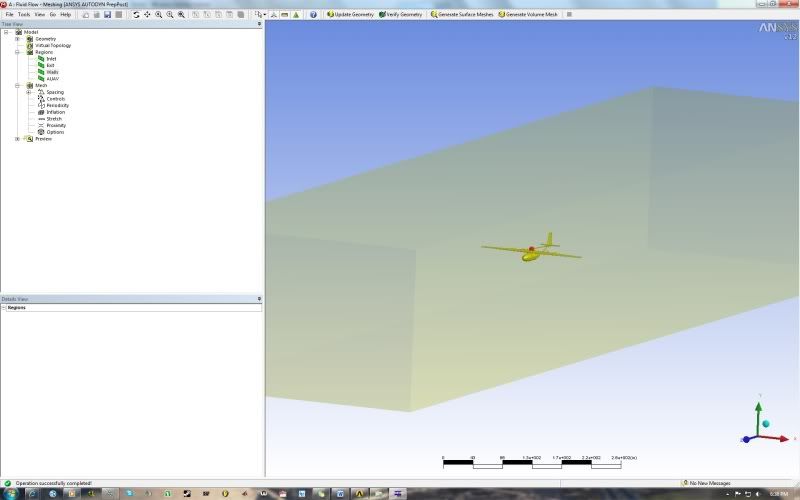 
Last edited by courtjester140; March 16, 2010 at 17:46. Reason: New Problem |
|

|

|
|
|
|
 Similar Threads
|
||||
| Thread | Thread Starter | Forum | Replies | Last Post |
| [ICEM] O-grid around wing geometry | Anorky | ANSYS Meshing & Geometry | 15 | November 27, 2017 13:43 |
| Importing CAD geometry and Editing edges to match | Ahmed | CFX | 15 | March 21, 2016 12:39 |
| [ICEM] Ship Hull imported geometry | nuovodna | ANSYS Meshing & Geometry | 0 | February 25, 2010 10:09 |
| Simulation of Flow through Complex 3D Geometry | EmersonKB | CFX | 5 | July 2, 2009 08:17 |
| vitual _ real | deneb | FLUENT | 3 | January 22, 2007 04:31 |


 Threaded Mode


