|
|
|
[Sponsors] | ||||
 May 2, 2016, 10:57
|
|
#21 | |
|
Senior Member
Join Date: Jun 2009
Posts: 174
Rep Power: 17  |
Quote:
|
||

|

|
||
|
May 2, 2016, 12:07
|
|
#22 |
|
Member
ngoc tran bao
Join Date: Jan 2016
Posts: 35
Rep Power: 10 |
Turbo, I think this picture will help, feel free to correct it if I'm wrong. |
|
|
|
|
|
|
May 2, 2016, 12:20
|
|
#23 | |
|
Senior Member
Join Date: Jun 2009
Posts: 174
Rep Power: 17 |
Quote:
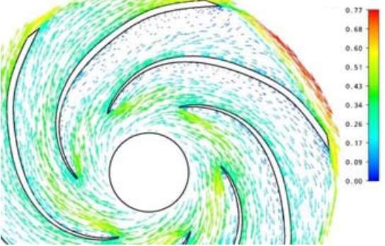
Have a look at leading-edge area. I see large flow separations on the suction side due to very high incidence from your part-load operation flow. No issues I see from your cfd. |
||
|
|
|
||
|
May 2, 2016, 21:52
|
|
#24 |
|
Member
ngoc tran bao
Join Date: Jan 2016
Posts: 35
Rep Power: 10 |
I have read some papers and I found that in their research the flow separation which occurs at suction side likes this below pic . On pressure side, the flow is attached on the blade and follows the curvature well (different from my pic) and that is the right behavior the flow should be.
|
|
|
|
|
|
|
May 3, 2016, 21:16
|
|
#25 |
|
Super Moderator
Glenn Horrocks
Join Date: Mar 2009
Location: Sydney, Australia
Posts: 17,781
Rep Power: 143 |
If your simulation is running at off-design conditions then all sorts of weird stuff happens.
If your simulation is not converged you can also get weird stuff happening. And finally, if your simulation is actually transient and you just look at a single frame of a transient simulation things can look weird as well. You might need to do a time average to get a good mean flow field. |
|
|
|
|
|
 |
|
|
 Similar Threads
|
||||
| Thread | Thread Starter | Forum | Replies | Last Post |
| [Help!] impeller torque calculation: pressure and viscous moments | ghost82 | Main CFD Forum | 1 | March 27, 2014 02:37 |
| how to compute relative velocity from absolute? | spk | Main CFD Forum | 3 | July 9, 2010 08:42 |
| Strange Velocity in impeller of MRFSimpleFOAM | waynezw0618 | OpenFOAM Running, Solving & CFD | 50 | December 21, 2009 09:45 |
| Velocity in Porous medium : HELP! HELP! HELP! | Kali Sanjay | Phoenics | 0 | November 6, 2006 06:10 |
| what the result is negatif pressure at inlet | chong chee nan | FLUENT | 0 | December 29, 2001 05:13 |
 2Likes
 Linear Mode


