|
|
|
[Sponsors] | ||||
 November 23, 2015, 07:03
|
|
#1 |
|
Senior Member
Join Date: Nov 2015
Posts: 135
Rep Power: 10  |
In CFX there u can simply chose 2 component labeling of ur fluid under the default domain TAB.
Where do I find the corresponding thing in fluent? |
|

|

|
|
|
November 24, 2015, 03:34
|
|
#2 |
|
Senior Member
Join Date: Nov 2015
Posts: 135
Rep Power: 10 |
Sorry but Im not quite familiar with the program and just couldnt find the right option. In my model I have two inlets and the air coming from each inlet I wanted to label differently. It's just a matter of how this is implemented in fluent. As far as I understood multiphase is a different thing concerning 2 real phases, but in my case I do not have 2 phases just 2 (basically identical) gases.
|
|
|
|
|
|
|
November 24, 2015, 03:38
|
|
#3 |
|
Senior Member

Rick
Join Date: Oct 2010
Posts: 1,016
Rep Power: 26 |
Hi,
I don't understand well your question. If you want to have 2 identical fluids (air), named differently, in the material tab copy air two times, so to have identical properties, then rename one of them.
__________________
Google is your friend and the same for the search button! 
|
|
|
|
|
|
|
November 24, 2015, 05:42
|
|
#4 |
|
Senior Member
Join Date: Nov 2015
Posts: 135
Rep Power: 10 |
Yeah but when running the simulation in the end I want to visualize the 2 different airparts, so that I can see how the 2 parts are mixing or not mixing well...
Is that even possible without fluent running the 2 different airparts seperately (or knowing before that he is supposed to "differ" the 2 fluids) ? The labeling u were talking about is enough in this sense and later in the results tab I can label everything by what I just defined in the material tab in the solution part of the program? I thought this tab (Materials) was just to define materials/fluids but didnt have any further purpose if I didn't specifically choose the 2. fluid in some other part like multiphase or similar?! |
|
|
|
|
|
|
November 24, 2015, 05:51
|
|
#5 |
|
Senior Member
Rick
Join Date: Oct 2010
Posts: 1,016
Rep Power: 26 |
I think you need a mutiphase approach to visualize the mixing of the 2 gases, but I'm not sure 100%.
__________________
Google is your friend and the same for the search button!
|
|
|
|
|
|
|
November 24, 2015, 15:20
|
|
#6 |
|
New Member
Nikola
Join Date: Dec 2014
Posts: 6
Rep Power: 11 |
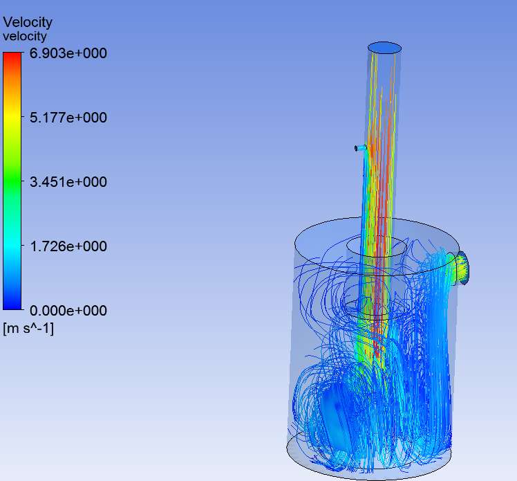
For qualitative indicator of mixing, you can try to use streamlines. You don't need to define new zones or anything. Just use equal spacing at the inlet and see how streamlines go.
In CFD Post, you can define multiple streamlines and if you choose a different color for each, you can make it easier to see. |
|
|
|
|
|
|
November 27, 2015, 05:26
|
|
#7 |
|
Senior Member
Join Date: Nov 2015
Posts: 135
Rep Power: 10 |
So within the CFD Post I can specify the streamlines coming from a certain inlet to be in some color range and the other streamlines in a different color range?
|
|
|
|
|
|
|
November 27, 2015, 06:35
|
|
#8 |
|
Senior Member
Rick
Join Date: Oct 2010
Posts: 1,016
Rep Power: 26 |
Yes, you can.
__________________
Google is your friend and the same for the search button!
|
|
|
|
|
|
|
December 2, 2015, 12:33
|
|
#9 |
|
Senior Member
Join Date: Nov 2015
Posts: 135
Rep Power: 10 |
|
|
|
|
|
|
|
December 2, 2015, 12:39
|
|
#10 |
|
Senior Member
Join Date: Nov 2015
Posts: 135
Rep Power: 10 |
Jesus Christ..Why is the text gone after I inserted the pictures????
Cool now I have to write everything again: To make it short: These pictures show the 2 different inlets: the small one has a set massflow of 0.003g/s the top open inlet has an order of 0.5g/s Now This result seems weird to me as one would expect mixing along the flow, but the simulation tells me the opposite? Is this reasonable? Im wondering if the equations incorporate the mixing or if the "selfdiffusion" has to be accounted for seperately or if these processes do not have anything to do with each other? What in this sense does multiphase stand for?: Is there meant to be 2 real phases like liquid and gaseous or can that also mean 2 "similar" gases ?! |
|
|
|
|
|
|
December 2, 2015, 14:02
|
|
#11 |
|
Senior Member
Bruno
Join Date: Mar 2009
Location: Brazil
Posts: 277
Rep Power: 21 |
Your results seem quite reasonable to me. You have a main inlet with a much higher velocity then you secondary inlet. There is no swirl. I see no reason for the fluids to mix more then they do.
If do want to see two different gases mixing, just do a multicomponent simulation (look for examples in the tutorials). The results should be pretty close to what you've got. Cheers |
|
|
|
|
|
|
December 3, 2015, 03:58
|
|
#12 |
|
Senior Member
Join Date: Nov 2015
Posts: 135
Rep Power: 10 |
Thank you for your answer. But doesnt diffusion play a role in mixing?
Is this accounted for in the equations? |
|
|
|
|
|
|
December 4, 2015, 05:32
|
|
#13 |
|
Senior Member
Bruno
Join Date: Mar 2009
Location: Brazil
Posts: 277
Rep Power: 21 |
It does. But in a simulation with just one fluid, the only diffusion you have is viscosity, since there is no mass fraction gradient. But even so, unless diffusion is really high and/or gas properties really different, it seems like advection will be the main effect in your case.
But them again, you can just do a multicomponent simulation and check it. Cheers |
|
|
|
|
|
|
December 4, 2015, 12:28
|
|
#14 |
|
Senior Member
Join Date: Nov 2015
Posts: 135
Rep Power: 10 |
Not quite sure whats wrong.
If I specify a mixture say 1. air 2. n2 in this order in the mixture-template then under the tab species of some inlet under boundary conditions the 2. one doesnt show up...Why is that? Also in this case, I cant choose "Full Multicomponent Diffusion" ?! |
|
|
|
|
|
|
December 4, 2015, 12:32
|
|
#15 |
|
Senior Member
Bruno
Join Date: Mar 2009
Location: Brazil
Posts: 277
Rep Power: 21 |
Because you only need to solve the mass fraction of one of the gases. The mass fraction of the second one is 1 minus the other.
|
|
|
|
|
|
|
December 4, 2015, 15:32
|
|
#16 |
|
Senior Member
Join Date: Nov 2015
Posts: 135
Rep Power: 10 |
Still 2 components implies diffusion, so why can't I choose "full multicomponent diffusion"
|
|
|
|
|
|
|
December 4, 2015, 15:49
|
|
#17 |
|
Senior Member
Join Date: Nov 2015
Posts: 135
Rep Power: 10 |

|
|
|
|
|
|
|
December 4, 2015, 15:50
|
|
#18 |
|
Senior Member
Join Date: Nov 2015
Posts: 135
Rep Power: 10 |
2 questions regarding the solving:
1. Whats this issue with the Mach number at the pressure-outlet-9??? Do I have to worry about it since the solution seemed to have converged...(The thing at the end is just another new run) 2. Why is he now only solving for air? Since I specified N2 as well shouldnt he also solve for N2 ? |
|
|
|
|
|
|
December 4, 2015, 19:35
|
|
#19 |
|
Senior Member
Join Date: Nov 2015
Posts: 135
Rep Power: 10 |
Just one other question:
When I specify the Inlet Mass Flow for example, Fluent already assumes that the flow has a stationary profile being zero on the border and higher in the middle.... I guess I could use velocity as boundary condition being fixed to a constant value (I want a plugflow) but then its not assured that the actually wanted massflow is constant. So how can I achieve both? |
|
|
|
|
|
|
December 7, 2015, 07:48
|
|
#20 | |||
|
Senior Member
Bruno
Join Date: Mar 2009
Location: Brazil
Posts: 277
Rep Power: 21 |
Quote:
Quote:
 , then you only need to solve for , then you only need to solve for  or or  , not both. Also, you should read the documentation. Under section 7.1.1, "Species Transport Equation": , not both. Also, you should read the documentation. Under section 7.1.1, "Species Transport Equation":Quote:
Cheers |
||||
|
|
|
||||
 |
|
|
 Similar Threads
|
||||
| Thread | Thread Starter | Forum | Replies | Last Post |
| Data Center Air conditioning Boundary Condition problem | jaypatel | OpenFOAM | 9 | April 8, 2020 15:04 |
| Radiation interface | hinca | CFX | 15 | January 26, 2014 17:11 |
| Modeling the mixing of air and kerosene in a flow channel | StefanG | CFX | 3 | June 11, 2012 20:21 |
| Simulation of air flow in a chamber | Issa | CFX | 3 | November 23, 2009 17:16 |
| air bubble is disappear increasing time using vof | xujjun | CFX | 9 | June 9, 2009 07:59 |


+ \nabla \cdot \left( \rho \vec{v} Y_i \right) =
-\nabla \cdot \vec{J}_i + R_i + S_i")


 Linear Mode


