|
|
|
[Sponsors] | ||||
 January 26, 2014, 05:37
|
|
#1 |
|
New Member
Join Date: Jan 2014
Posts: 3
Rep Power: 12  |
I am extremely frustrated. I have been at this for weeks with little to no success.
I am trying to create a 2D mesh to simulate air flow over the S809 airfoil. I used coordinates from the NREL website. I have mainly tried following this tutorial: https://confluence.cornell.edu/displ...oil+-+Geometry. However, I am running into two major problems. 1) First problem, when I try to create the vertical line for the projection that will separate the domain (Under Creating Quadrants in the tutorial), I receive a Boolean error. 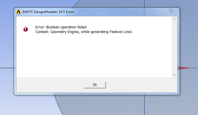 I have figured this comes from ANSYS not being able to read the geometry of the coordinates perfectly. Therefore, I use a spline to create the airfoil from imported points instead of importing the curve directly from the coordinates file. However, I end up with a less than perfect airfoil shape. I have figured this comes from ANSYS not being able to read the geometry of the coordinates perfectly. Therefore, I use a spline to create the airfoil from imported points instead of importing the curve directly from the coordinates file. However, I end up with a less than perfect airfoil shape.If anyone has a better solution or an actual fix to this error, that would be great. 2) Second problem. The S809 is not symmetrical like the NACA profiles. Therefore, when I create the horizontal line, for the quadrants it separates the bottom the airfoil into two sections. If you are having trouble understanding this look at this picture. 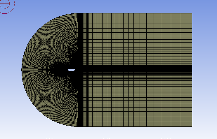 The effects of the separation is very noticeable when I try to mesh. The effects of the separation is very noticeable when I try to mesh. 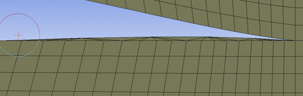 All in all these problems either lead to errors that cause simulation to crash or bad results when trying to validate. I am an undergraduate student in over my head, if you could please keep in mind with your answer that I have taken no CFD courses. If anyone has any tutorials similar to the cornell tutorials for S809 that would be great. Or even a link to a sample geometry and mesh of the S809 that would help me understand would be great as well. Honestly, any help at all, would be awesome. Thank you |
|

|

|
|
|
January 26, 2014, 10:22
|
|
#2 |
|
Super Moderator

Alex
Join Date: Jun 2012
Location: Germany
Posts: 3,399
Rep Power: 46 |
Concerning number 2, you have several options.
You could perform the split operations in a different order, e.g. first do the vertical split at the trailing edge. This way you can choose only the body "behind" the airfoil for the horizontal split. Or you could simply do another boolean operation (unite) with the small volume that is created when you do the horizontal split. Or you could use a bottom-up approach instead, with a separate sketch for each of the parts. |
|
|
|
|
|
|
January 26, 2014, 16:49
|
|
#3 |
|
New Member
Join Date: Jan 2014
Posts: 3
Rep Power: 12 |
Thank you for your response Flotus1
Problem number 1 stops me from completing a vertical split, unless I offset the vertical line by .0001 meters. Which is what I did. Now that I have done, that, how do I create an effective mesh on the dome part of the mesh, that contains the airfoil? Seeing how the tutorial calls for the creation of 4 sections, instead of the 3 I have now when I take your advice. As for your other suggestion, the bottom up approach, I am not sure what you mean by that. |
|
|
|
|
|
|
January 27, 2014, 02:57
|
|
#4 | ||
|
Super Moderator
Alex
Join Date: Jun 2012
Location: Germany
Posts: 3,399
Rep Power: 46 |
Quote:
Did you try to merge the small part instead? unite.jpg Quote:
The opposite way would be a bottom-up approach where you create a separate sketch for each of the four blocks you want to have in the end. While creating the surfaces from these 4 sketches, make sure to use the "add frozen" option. Otherwise the geometry will be merged again. frozen.png When you are done, select the 4 surfaces together, right-click and choose "form new part". If you dont, you will get interfaces instead of a continuous mesh. |
|||
|
|
|
|||
|
February 5, 2014, 15:34
|
|
#5 |
|
New Member
Join Date: Jan 2014
Posts: 3
Rep Power: 12 |
Thanks Flotus1, your suggestion about bottom up really did the trick! You are the man!
|
|
|
|
|
|
|
May 24, 2016, 13:34
|
|
#6 | |
|
New Member
J SB
Join Date: Aug 2015
Posts: 6
Rep Power: 10 |
Quote:
I really appreciate any help you can provide (you or anyone) Last edited by fluenter2015; May 27, 2016 at 11:18. |
||
|
|
|
||
 |
|
|

 Linear Mode


