|
|
|
[Sponsors] | ||||
 June 5, 2014, 18:52
|
|
#1 |
|
New Member
Ty Huntington
Join Date: May 2014
Posts: 2
Rep Power: 0  |
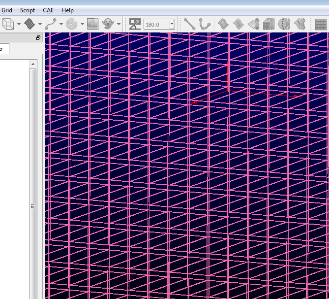
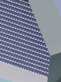
Hey everyone, I have created a honeycomb type structure in Catia and have imported it into pointwise as an iges file. However, I'm wondering if there is an easy/easier way to mesh the structure in the pics below that will not take ages and ages by doing each cell manually? Thanks for any help in advance.
|
|

|

|
|
|
June 6, 2014, 08:48
|
|
#2 |
|
Senior Member
|
My suggestion for your case is using Glyph scripting for meshing one cell, and then copying and pasting the mesh along the x and y direction in order to create the entire honeycomb grid.
You might do copying and pasting manually by pressing "Ctrl+C" and "Ctrl+V", and then going to the Translate, but still it is time consuming. If you think that writing a script would be difficult, you can use journaling capability. To this end, go to the "Script" after importing your geometry, select "Begin Journal", type a name for your journal. Rest of steps are indicated in the following in order. 1- Then, create a mesh for one cell by using the GUI and indicate your wall boundaries by appropriate names, cause at the end you will have a lots of walls. Respectively, specify your boundary conditions for this cell. 2- Press "Ctrl+C", "Ctrl+V", and then go to the Translate. Indicate your translation, and do translate. 3- Go to the "Script", select "Add Comment to Journal" and type "Cell number 1", which will indicate this part of journal corresponding to this cell. 4- Go to the "Script", select "End journaling". 5- Open your journal file with for example Notepad++ which allows you to manage your script pretty well. After, copy the part of the script that you use for creating the mesh, which means in this case, all the part except the first little part which indicates the Glyph package. Then, paste it right after the last line. 6- Change the specification of the translation for the pasted part which indicates the next cell, also change the name of the cell in the comment line, in this case, "Cell number 2". 7- After this, you can continue copying and pasting this part of the journal and changing the translation specification for each cell until you get the entire grid, or you can put it into a loop that needs a little scripting. If you are interested in scripting you will find almost everything in the Glyph man page 2 which is available through Poitwise webpage. Good Luck, Payam |
|
|
|
|
|
|
June 6, 2014, 10:17
|
|
#3 |
|
New Member
Ty Huntington
Join Date: May 2014
Posts: 2
Rep Power: 0 |
Thank you very much for the detailed reply Payam. I will give this a go immediately and post the results after I figure it out. I might do a small section with some modified geometry to get a feel for those techniques first.
|
|
|
|
|
|
|
June 7, 2014, 13:45
|
|
#4 |
|
Senior Member
Chris Sideroff
Join Date: Mar 2009
Location: Ottawa, ON, CAN
Posts: 434
Rep Power: 22 |
Or if the geometry is not changing in the flow direction, simply create a 2D mesh on the cross-section and then create the volume mesh using a translational extrusion.
|
|
|
|
|
|
|
June 7, 2014, 18:06
|
|
#5 |
|
Senior Member
|
Hello again,
I got some time, so I just gave my previous post a try. Although I wrote a simple script, you can still fill the loops with your journal or modify the script based on your needs. Please find the script in the attachment in addition to some images which illustrate its usage. Please note, if you are trying journaling, cut and paste instead of copy and paste. In the script you will find the definition of the parameters, including horizontal and vertical edges length of the cells, horizontal and vertical side length of the surrounding frame, angle between the horizontal and vertical side of the frame, and horizontal and vertical space between the cells. I suppose that the cells have rectangle cross section profile. In the line 73 and 74 you can adjust the translate extrusion distance and number of the extrusion steps. Good Luck, PDP Here is the script: Code:
# Defining the parameters
# --------------------------------------------------------------------------------------------------
# l defines the horizontal side length of the quadrilateral frame which surrounds cells
set l 3.0
# h defines the vertical side length of the quadrilateral which surrounds cells
set h 2.0
# dx defines the horizontal space between cells
set dx 0.05
# dy defines the vertical space between cells
set dy 0.05
# A defines the horizontal edge length of a cell; cells are considered to have rectangle section
set A 0.1
# B defines the vertical edge length of a cell
set B 0.1
# a defines the angle between the horizontal and vertical side of the quadrilateral frame
set a 70.0

# Setting default parameters
# --------------------------------------------------------------------------------------------------
set pi2 6.2831853071795862
set xorig 0.0
set ll $l

# Looping for cell creation
# --------------------------------------------------------------------------------------------------
for {set k 0} {[expr $k*($B+$dy)] <= $h} {set k [expr {$k+1}]} {
	set con {}
	for {set j 0} {[expr $j*($A+$dx)] < $ll} {set j [expr {$j+1}]} {
		set v "[expr $j*$A] 0 0"
		set dv "[expr $j*$dx] 0 0"
		set dz "0 0 1"
		set xorig [expr ($k*($B+$dy))/tan(($a*$pi2)/360.)]
		set yorig [expr {$k*($B+$dy)}]
		set transVect [pwu::Vector3 add $v $dv]
		# Creating the section profile of the cells, in this case, it is rectangle
		# -----------------------------------------------------------------------
		set x[list [expr {$xorig-($A+$dx)}] [expr {$xorig-$dx}] [expr {$xorig-$dx}] [expr {$xorig-($A+$dx)}] [expr {$xorig-($A+$dx)}]]
		set y[list [expr {$yorig-($B+$dy)}] [expr {$yorig-($B+$dy)}] [expr {$yorig-$dy}] [expr {$yorig-$dy}] [expr {$yorig-($B+$dy)}]]
		set z 0.0
			for {set i 0} {$i <= 3} {set i [expr {$i+1}]} {
				set linePts($i) [pw::SegmentSpline create]
					$linePts($i) addPoint[list [lindex $x $i] [lindex $y $i] $z]
					$linePts($i) addPoint[list [lindex $x [expr int($i+1)]] [lindex $y [expr int($i+1)]] $z]
				set lineCon($i) [pw::Connector create]
					$lineCon($i) addSegment $linePts($i)
					$lineCon($i) setDimension 10
				lappend con $lineCon($i)
				# translation
				# -----------
				pw::Entity transform [pwu::Transform translation $transVect] $lineCon($i)
				}
		if {$j > 0} {
			# domain creation
			# ---------------
			set domc[list [lindex $con [expr int($j*4)]] [lindex $con [expr int($j*4)+1]] [lindex $con [expr int($j*4)+2]] [lindex $con [expr int($j*4)+3]]]
			set dom [pw::DomainStructured createFromConnectors $domc]
			# domain extrusion for block creation
			# -----------------------------------
			set block [pw::BlockStructured create]
				set strface [pw::FaceStructured create]
				$strface addDomain $dom
				$block addFace $strface
					set strblock [pw::Application begin ExtrusionSolver $block]
						$block setExtrusionSolverAttribute Mode Translate
						$block setExtrusionSolverAttribute TranslateDirection {0 0 1}
						$block setExtrusionSolverAttribute TranslateDistance 0.1
			$strblock run 10
			$strblock end
			}
	}
set ll [expr {($l - tan((($a+90.0)*$pi2)/360.) * ($k*($B+$dy)))-$xorig}]
}

# view
# --------------------------------------------------------------------------------------------------
set view [pw::Display getCurrentView]

# End of the script
|
|
|
|
|
|
 |
|
|
 Similar Threads
|
||||
| Thread | Thread Starter | Forum | Replies | Last Post |
| mass flow in is not equal to mass flow out | saii | CFX | 12 | March 19, 2018 05:21 |
| [ICEM] ICEM Blocking and Meshing - Flow over Periodic Hill | Crank-Shaft | ANSYS Meshing & Geometry | 8 | April 29, 2014 03:11 |
| [ICEM] Meshing External Flow Tanker | rzhang | ANSYS Meshing & Geometry | 2 | February 2, 2014 20:50 |
| Meshing for Mutliphase free surface flow | MatzeMas | ANSYS | 2 | August 7, 2009 05:06 |
| FLOW 3D Meshing | AMP | FLOW-3D | 6 | October 1, 2008 11:07 |
 1Likes
 Linear Mode


