|
|
|
[Sponsors] | ||||
 October 7, 2010, 21:03
|
|
#1 |
|
New Member
David Stuart
Join Date: May 2010
Location: Newcaslte Australia
Posts: 15
Rep Power: 15  |
Hi All,
I hope that someone might be able to shed light on this for me. I am trying to simulate flow over a wing that I have modelled in Pro Engineer. Its an unusual wing section, as its a flex wing (microlight wing). As far as I can see in pro eng, there are no problems with the model at all... I intend to mesh all my simulations for this project in ICEM, however I thought I'd throw it in into CFX mesher while I learn the finer details of ICEM and get a simulation running (all be it a rough one). Using the CFX mesher, I get a problematic geometry warning aftert trying to mesh. I have run a test with the same wing section as the root section of my proper model (exactly the same), extruded to make a small section of wing to test my theory that the thin extension of the wings upper surface was the problem (thought it may be thiner than CFX liked and the cause of my problems). However this meshed withought a problem at all... So now I am not sure where to look. I thought that it must be a model/CAD problem but if CFX doesnt have a problem with the section shape, as prooven in the test I did Im not all that sure. The model is a swept blend feature between 25 sections that are parametricly controlled so it is quite complex, however it does behave well in pro eng so Im not sure that its simply the CAD side of things causing issues... I thought that I'd post this and see if anyone has other ideas while I spend some time sorting through my model to look for anything that might be the cause. some pics... The model (of which only 1/2 is used to take advantage of symmetry)  and a close up of the tip 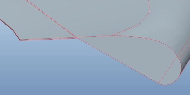 You can see that in the first three pics the problem is at the thin extension to the upper wing surface. It seems to be missing the top of this section in the second and third image. where as in the 4th image it seems that the top surface has been merged into the bottom, where the blue line is the edge of the top surface and the red is the bottom.  The wing as a whole 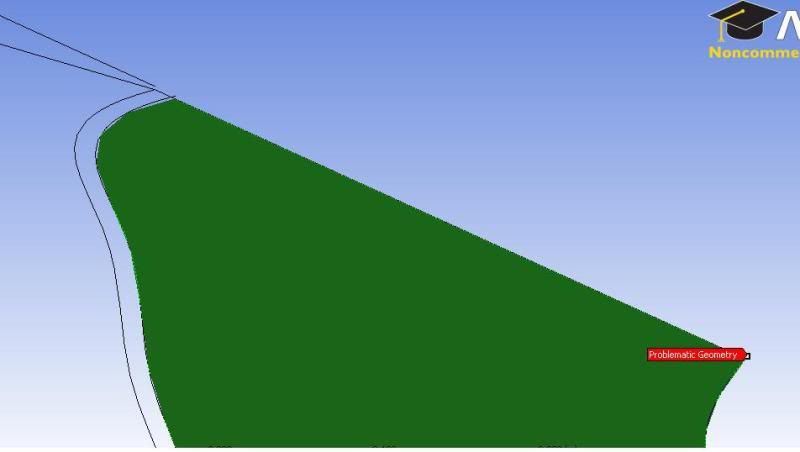 Wing root section looking at the junction between the "thick" part of the wing and the thin extension... Hope that makes sense. 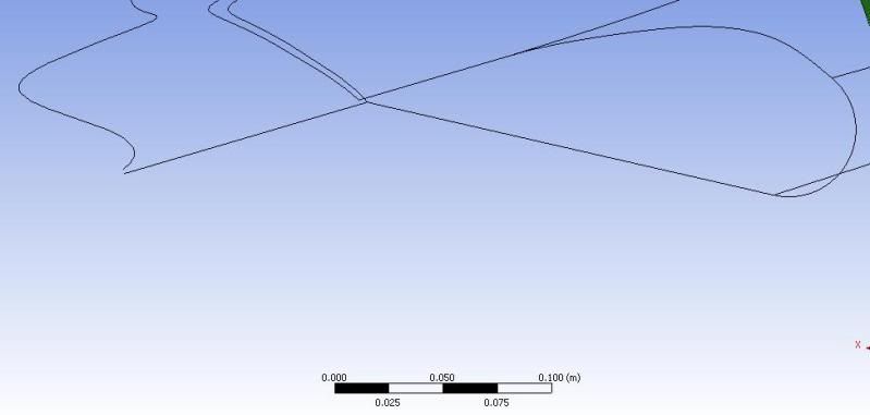 Tip section, hard to see as wire frame...however note that the top surface of the thin extension to teh trailing edge is missing and that the bottom surface corner is missing... 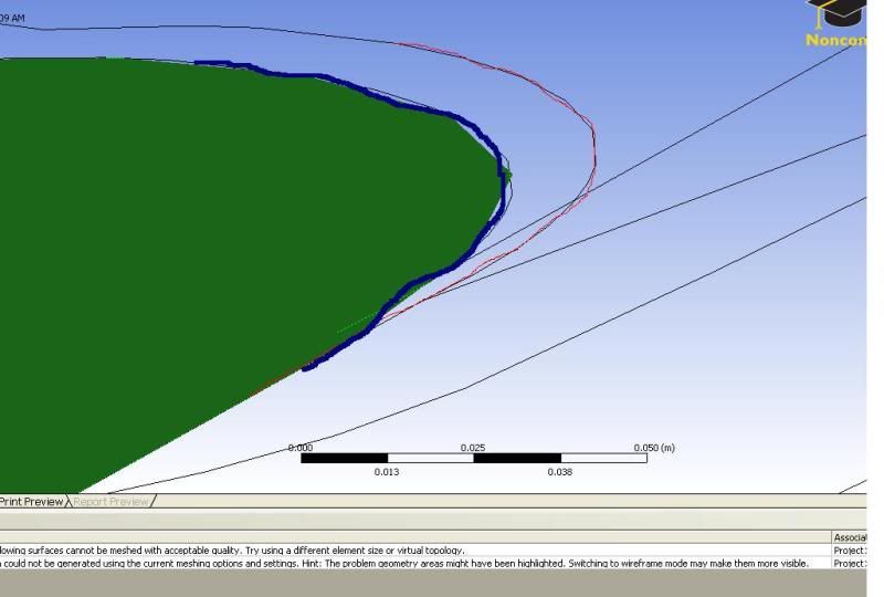 This picture suggests that the top surface is merged into the bottom surface, Made me think that the thickness (2mm) of this section was too thin for CFX to handle and went on to try a test of teh section (below) 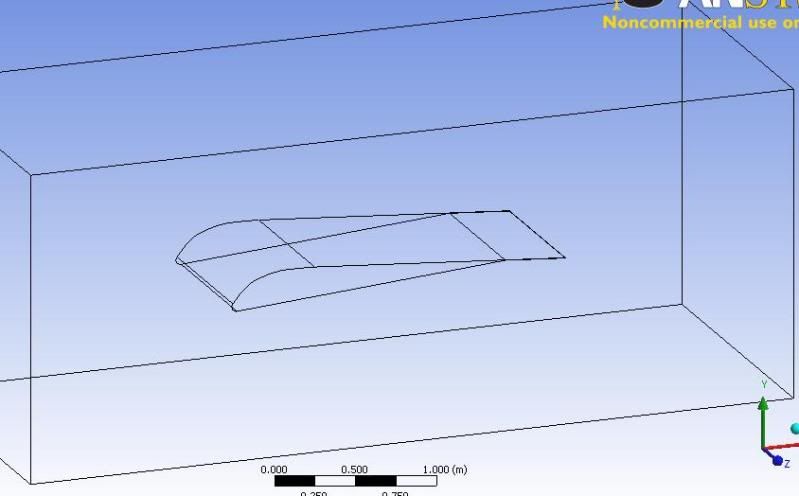 Root section extruded to test the geometry... exactly the same method of set up as the whole wing. 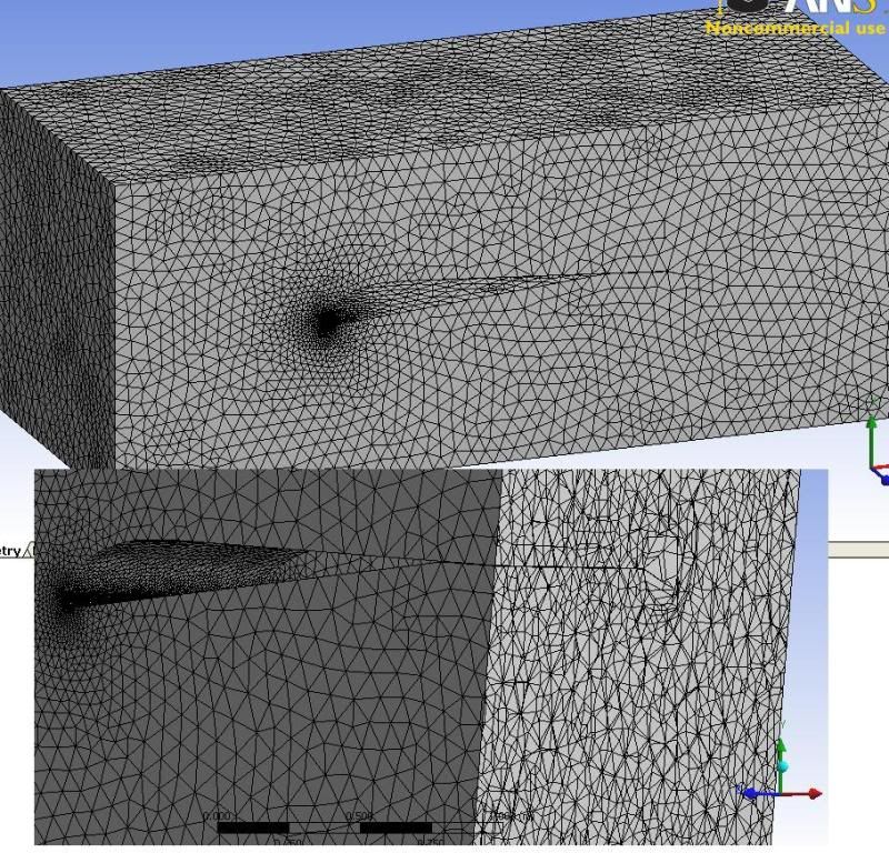 No problem at all, note that the this section has been captured fine. 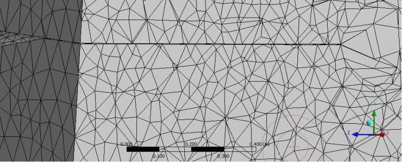 I should Also add that I have had this model in ICEM and found a similar problem where the geometry just doesnt look/feel right after importing as STEP or IGES... however I'm only learning ICEM so Im not sure whats really going on. |
|

|

|
|
|
October 7, 2010, 21:46
|
|
#2 |
|
Super Moderator
Glenn Horrocks
Join Date: Mar 2009
Location: Sydney, Australia
Posts: 17,703
Rep Power: 143 |
This will be tricky geometry to mesh in any package. Do you need to mesh the internal cavity? Things will be MUCH easier if you don't have to.
If you must mesh the internal cavity then I doubt you will be able to do this well in the default tools. You will need the flexibility and power of ICEM - and the big learning curve before you can drive it properly. If you don't need to model the internal cavity the problem is much easier. It would be better done in ICEM but the normal ANSYS tools can probably do it if you must. Don't forget the tricky bit is when you put the prism layers on the wing and you have not even attempted that yet so it you are having problems with the tet mesh you have no chance with the prism layers. |
|
|
|
|
|
|
October 7, 2010, 22:09
|
|
#3 |
|
New Member
David Stuart
Join Date: May 2010
Location: Newcaslte Australia
Posts: 15
Rep Power: 15 |
No the cavity doesnt need meshing. I always intended on working with ICEM for this, but I thought I'd try and get a sneek peak using ANSYS mesher in CFX while I play with ICEM.
ghorrocks, I appreciate you comments, but do you have any ideas where I might find a solution to this problem? |
|
|
|
|
|
|
October 8, 2010, 05:21
|
|
#4 |
|
Super Moderator
Glenn Horrocks
Join Date: Mar 2009
Location: Sydney, Australia
Posts: 17,703
Rep Power: 143 |
My suggestions are I wrote above. Remove the inner cavity and things will get MUCH easier. A finer mesh should also make things easier, but take longer. I see your mesh is currently very coarse.
Finally, do lots of tutorials in ICEM and give it a go. It is much more powerful and flexible than the ANSYS WB meshing tools. But it has a big learning curve before you can drive it competently so expect to spend a bit of time getting up to speed. |
|
|
|
|
|
|
October 8, 2010, 19:41
|
|
#5 |
|
New Member
David Stuart
Join Date: May 2010
Location: Newcaslte Australia
Posts: 15
Rep Power: 15 |
Thanks ghorrocks, I'm a little confused still becasue I am not meshing the internal cavity.
Apart from that, as I said I plan to use ICEM so this week I'll be going through the tutorials for it. I take it from your posts that you dont have any reason to believe its the actual geometry causing hte problem rather than the meshing method? thats good news i guess... Thanks again. |
|
|
|
|
|
|
October 9, 2010, 05:56
|
|
#6 | |
|
Super Moderator
Glenn Horrocks
Join Date: Mar 2009
Location: Sydney, Australia
Posts: 17,703
Rep Power: 143 |
Quote:
My experience with ANSYS WB meshing tools is meshing airfoils with them is a challenge. Once you get the hang of ICEM it is much better for this sort of stuff. |
||
|
|
|
||
|
October 11, 2010, 02:32
|
|
#7 |
|
New Member
David Stuart
Join Date: May 2010
Location: Newcaslte Australia
Posts: 15
Rep Power: 15 |
OK cool, thanks. Im worried that its possible there's a hidden problem but I will see later this week after I have played a little more with ICEM. Cheers,
I'll let you know how it goes. |
|
|
|
|
|
|
October 12, 2010, 12:03
|
|
#8 |
|
Member
andres
Join Date: Sep 2010
Posts: 44
Rep Power: 15 |
Hi people! I have the same problem "problematic geometry"
How did you solve it?¿ thanks |
|
|
|
|
|
|
October 12, 2010, 13:53
|
|
#9 | |
|
Senior Member
Michael P. Owen
Join Date: Mar 2009
Posts: 196
Rep Power: 17 |
Quote:
There are some other things that could be done to repair the geometry if you have a Design Modeler license. |
||
|
|
|
||
|
October 12, 2010, 18:21
|
|
#10 |
|
New Member
David Stuart
Join Date: May 2010
Location: Newcaslte Australia
Posts: 15
Rep Power: 15 |
michael_owen,
I was leaning towards it being geometry, thanks for the confirmation. The wing is symmetric about it's centreline, so I am only meshing one half the span. but the wing section itself is not symetric (as you can see from the few pictures I included in the first post). Any Idea what the issue is? I had a gut feeling that becasue the geometry works in pro_Eng as a .prt, there must be something funky happenning when I convert it to a step/iges but Im only guessing. If so, can proEng geometry be sent directly to ICEM as it can to workbench without converting to another file type? I do have access to DModeler, what can be done there? Thanks for you help |
|
|
|
|
|
|
October 12, 2010, 18:33
|
|
#11 |
|
Super Moderator
Glenn Horrocks
Join Date: Mar 2009
Location: Sydney, Australia
Posts: 17,703
Rep Power: 143 |
I always use parasolid as my preferred format to import into ANSYS. Parasolid is the native geometry kernal of ANSYS.
|
|
|
|
|
|
|
October 12, 2010, 18:35
|
|
#12 |
|
New Member
David Stuart
Join Date: May 2010
Location: Newcaslte Australia
Posts: 15
Rep Power: 15 |
Ok thanks, I will try that.
|
|
|
|
|
|
|
October 12, 2010, 20:01
|
|
#13 |
|
Senior Member
Michael P. Owen
Join Date: Mar 2009
Posts: 196
Rep Power: 17 |
Yes, try parasolid. Also, yes, there is a Pro/E geometry interface for ICEM.
The underlying problem is not correctly converting it's internal representation of the geometry. This can happen with NURBS geometry with a lot of complex curvature, or a lot of surface patches, shared topology, etc. It may be that Pro/ cannot properly convert your geometry to ANY format. In that case your best bet is to use Design Modeler to repair the broken geometry, for example by performing the same operations used to create the defective regions using native DM operations. |
|
|
|
|
|
|
October 12, 2010, 20:44
|
|
#14 |
|
New Member
David Stuart
Join Date: May 2010
Location: Newcaslte Australia
Posts: 15
Rep Power: 15 |
OK so I'll try parasolid first. If not, as I understand it, you mean import my Pro/ geometry into DM and rebuild the missing parts onto it?
Again thanks for your help on this everyone, really appreciate it. |
|
|
|
|
|
|
October 12, 2010, 23:54
|
|
#15 |
|
New Member
David Stuart
Join Date: May 2010
Location: Newcaslte Australia
Posts: 15
Rep Power: 15 |
OK, some good news I think.
So I looked at exporting as parasolid, or as michael_owen suggested, looking into if pro eng was improperly converting to other file types by looking at the geometry in Rhino and found problems doing both. so... Having considered that the wing geometry by itself behaves fine in proE, but the wing within the far field falls over in CFX/ICEM I thought about the process used to make the negative volume (cavity pocket application in pro Eng). When I make the assembly in pro eng the geometry is fine untill i create the cavity by removing the wing from the far field part. Even in pro/ the geometry highlighted above isn't captured in the cavity pocket. So i exported it before making the cavity and it meshed fine. I went through a few ICEM tutorials yesterday and If im not mistaken I can still mesh this having not created a cavity within the far field at the CAD level. I can remove that block within ICEM?... If so, im almost there. I'll let you know how it goes. [edit] I think that the problem has been solved so long as I can remove the block associated with the wing solid body from the volume mesh. I managed to make a volume mesh this afternoon, with some very rought rumbers on sizing. I found that (I believe) by coincidence that part of the wing was not meshed although the geomtry has been imported fine. I think its just a matter or getting my blocking strategy right now.That first rough go I had I only blacked around the wing as a whole, but I think it will need more detailed blocking to pick up the geomtry better. I think I will just go ahead and continue to do more tutorials in ICEM now to get a better feel for blocking 3D geomtry, any suggestions in the mean time on blocking strategy for this are very welcome. Cheers again for all your help/advice. Last edited by fatb0y; October 13, 2010 at 03:01. |
|
|
|
|
|
|
October 13, 2010, 17:17
|
|
#16 |
|
Member
andres
Join Date: Sep 2010
Posts: 44
Rep Power: 15 |
well, you have several approach a solution.
1. create virtual topology (it would put several edges or faces together and so it will solve the problem) 2. use another method that better fits to your geometry (I first start by playing with minimun and maximum cell/faces size. And if it doesn´t work then try another method. Pach independent it would be an option. 3. change your CAD geometry. But before changing your geometry try with 1. and 2. be patient. this site: http://www.msi.umn.edu/~porter/ansys...als/index.html used to be a great deal of mesh tutorials. It tought me a lot. but I think it is not available anymore. if you still have problems, send me your geometry and I would check it out. another thing... if you are using Ansys WorkBench Mesh, you have the possibility to go to CFX mesh by pressing right button on your mouse in the tree "mesh" and within CFX you will be able to better know where your problem come from. I hope it helps you hugs |
|
|
|
|
|
 |
|
|
 Similar Threads
|
||||
| Thread | Thread Starter | Forum | Replies | Last Post |
| problematic geometry | Electrico | ANSYS Meshing & Geometry | 2 | October 22, 2013 11:52 |
| problematic geometry | Electrico | FLUENT | 0 | May 3, 2010 12:15 |
| Problematic geometry error | Jenny | FLUENT | 4 | March 7, 2007 19:54 |
| vitual _ real | deneb | FLUENT | 3 | January 22, 2007 04:31 |
| Problematic geometry reported | smillerhh | FLUENT | 1 | December 7, 2006 11:42 |

 Linear Mode


