|
|
|
[Sponsors] | ||||
 February 24, 2016, 09:51
|
|
#1 |
|
Senior Member
Join Date: Nov 2015
Posts: 135
Rep Power: 10  |
When Specifying the boundary conditions in Fluent when working with species one has to give a value for the mass fraction through that inlet or outlet.
Now I'm wondering whether this value is really fixed to the one I supply or not? At the Inlet I add the mixture I sure know the composition but at some pressure-outlet I want it to be the result of the calculation since its sth I'm also interested in in the later process...So What meaning does this boundary condition have when it shouldn't be a previously fixed value but rather an outcome of the solution? It seems when I specify the total outflow through that outlet fluent tries to abide by that, but a specific species?!? |
|

|

|
|
|
February 26, 2016, 10:00
|
|
#2 |
|
Senior Member
Join Date: Nov 2015
Posts: 135
Rep Power: 10 |
So do boundary conditions not necessarily have to be fulfilled upon the calculation?
|
|
|
|
|
|
|
February 27, 2016, 08:40
|
|
#3 |
|
Senior Member
Lucky
Join Date: Apr 2011
Location: Orlando, FL USA
Posts: 5,675
Rep Power: 66 |
You must specify the species in case there is back-flow into the domain (and your outlet becomes an inlet). Otherwise, the backflow species is ignored if there is no backflow.
At an "outlet" you hope that everything actually does go out but you may solve a problem and find that there must be flow entering at certain locations. |
|
|
|
|
|
|
February 27, 2016, 14:42
|
|
#4 |
|
Senior Member
Join Date: Nov 2015
Posts: 135
Rep Power: 10 |
So how are boundary conditions treated during calculation?
Are they forced at each iteration or what impact do they have on the calculation? Coz the set boundary conditions do not necessarily mean that the solutions converges to the solution fulfilling these boundary conditions? |
|
|
|
|
|
|
February 27, 2016, 15:12
|
|
#5 | |
|
Senior Member
Join Date: Nov 2015
Posts: 135
Rep Power: 10 |
Quote:
The specified massflow and the mass fraction in the species tab at the boundary conditions do not refer to backflow, or? That's what I'm confused about. Are boundary conditions actually boundary conditions (like in my question above) or what are they if not fixed by each iteration? When solving a problem analytically, the boundary conditions are in the end manually forced to fix the general solution. How is that implemented here? How can a problem in the end come out with a backflow when I specify that there shouldn't be one? |
||
|
|
|
||
|
February 27, 2016, 15:22
|
|
#6 | |
|
Senior Member
Lucky
Join Date: Apr 2011
Location: Orlando, FL USA
Posts: 5,675
Rep Power: 66 |
Can you provide an example of how the solution fails to meet the boundary condition?
Quote:
Explicit boundary conditions are imposed directly onto the coefficient matrix and these are imposed and fixed with every iteration. Explicit boundary conditions applies to primitive variables like pressure, velocity, temperature, concentration, etc. Boundary conditions derived from these primitive variables are handled in various ways. For example, fluxes, gradients depends on the discretization scheme but can still be imposed directly on the coefficient matrix (of the massive linear system that Fluent solves every iteration). Advective fluxes are generally upwind-type discretizations and diffusive fluxes generally use central differencing. You pick the coefficients of your matrix to satisfy these boundary conditions in a way that is consistent with your discretization scheme. Then there are weak boundary conditions, these are usually iterated outside the iteration loop. These are not really boundary conditions but constraints that the boundary conditions must satisfy. For example a mass-flow outlet is actually a pressure outlet, where the outlet pressure is iterated every iteration to achieve the desired mass-flow rate. A mass-flow inlet is similar. |
||
|
|
|
||
|
February 27, 2016, 15:42
|
|
#7 | |||
|
Senior Member
Lucky
Join Date: Apr 2011
Location: Orlando, FL USA
Posts: 5,675
Rep Power: 66 |
Quote:
Quote:
Quote:
|
||||
|
|
|
||||
|
February 27, 2016, 17:21
|
|
#8 |
|
Senior Member
Join Date: Nov 2015
Posts: 135
Rep Power: 10 |
http://www.directupload.net/file/d/4...5cn5ur_png.htm
I uploaded the outlet where I have backflow. The hole in the middle is not due to "clip to range" but actually the flow cant go there because there is material. So the Outlet looks like a hollow cylinder. For Backflow values I worked with: Backflow Total temperature: 300K Backflow turbulent Intensity: 5% Backflow turbulent Viscosity Ratio: 10 These are the standard values. Now is it possible to specify these values such that I do not have backflow? It seems like the backflow is at the outer border (red). Shouldn't it be possible for the solution to flow out over the entire cylinder? The problem is cylindrically symmetric. BTW: Another question I have, if Inlet temperature is 300K but Operating Tempereature 288K the system seems to stay at 300K which is reasonable since the flow comming in is 300K, but what do I need the Operating Temperature for then? |
|
|
|
|
|
|
February 27, 2016, 19:48
|
|
#9 | |
|
Senior Member
Join Date: Nov 2015
Posts: 135
Rep Power: 10 |
Quote:
Mass Flow Rate (g/s) -------------------------------- -------------------- injectioninlet 0.012500001 nozzleoutlet -0.020498386 openinlet 0.10623819 pumpoutlet -0.098212912 ---------------- -------------------- Net 2.6892736e-05 injectioninlet is fine: boundary condition given: 0.0125 nozzleoutlet also fine: given: 0.0205 openinlet: well its open, so nothing given but pumpoutlet the thing which is shown in the above plot is actually given by 0.388g/s and not 0.098212912 |
||
|
|
|
||
|
February 27, 2016, 23:10
|
|
#10 | |
|
Senior Member
Lucky
Join Date: Apr 2011
Location: Orlando, FL USA
Posts: 5,675
Rep Power: 66 |
Quote:
If you have backflow where you don't expect there to be a backflow, it is a hint that something else is wrong with your problem setup. It could be something simple, such as boundary conditions being applied incorrectly. E.g. you apply a pressure outlet in a domain where physically there would be additional piping, etc that follows. If you expect the solution to be cylindrically symmetric and you are not getting this, then that is also a hint that something is amiss. It could be you have a bad mesh. The operating temperature option is specific to the Boussinesq model. I recommend reading about the Boussinesq model or the Fluent manual. The deviation of the local temperature from the reference temperature is what gives you your density change and buoyancy force. Also, unless gravity is aligned with the pipe axis, this problem cannot be cylindrically symmetric. |
||
|
|
|
||
|
February 28, 2016, 06:57
|
|
#11 | |
|
Senior Member
Join Date: Nov 2015
Posts: 135
Rep Power: 10 |
Quote:
When importing my model in the design modeller it somehow chose the axis of symmetry to be the x-axis :-/ But it shouldnt matter as long as I have the correct gravity direction, or are there other implicit assumptions which by convention go along the z-axis? What about the "radial equilibrium pressure distribution"? As far as I understand he assume radial symmetry,right? But along which axis? one more basic question to pressure outlet: Apart from the fact the there is not other outlet (well there is outflow, but I guess thats something else): when would u use a pressure outlet? U said the pressure is iterated at a pressure outlet to meet the mass flow, right? Though I thought the pressure is calculated with the other primitive variables I dont see how that pressure adaption is done to meet the mass flow... I mean that changes the pressure field which was an outcome of the iteration ?! Boussinesq is only available for fluids, not for mixtures right? Coz I can only find it in the fluid materials not in the mixture. (I'm using kinetic theory for the mixture at other drop down menus and that changes the fluid drop down menus of the substances under the mixture to these L-J-Paramters) |
||
|
|
|
||
|
February 28, 2016, 14:01
|
|
#12 |
|
Senior Member
Join Date: Nov 2015
Posts: 135
Rep Power: 10 |
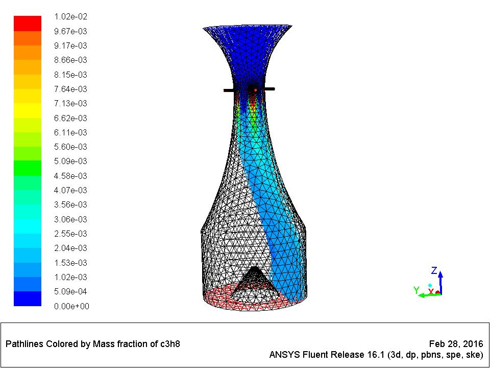 So to give you an example of what it looks like. Atm in this picture I used the outlet at the bottom as a pressure outlet and the top inlet as a mass-flow-inlet, becoz the other way around I never got the required mass-flow i specified at the outlet. This way it works but still: shouldn't it surround the nozzle in the middle (which also has an outflow specified by the boundary condition) symmetrically? |
|
|
|
|
|
|
February 29, 2016, 08:54
|
|
#13 |
|
Senior Member
Join Date: Nov 2015
Posts: 135
Rep Power: 10 |
maybe just another remark: when I let it run from standard initialization with standard completion residual=1e-3 then everything looks symmetric without backflow. its just when I decrease the error tolerance for example to 1e-4 and let it run for much longer when this starts to occur. Is it reasonable? Or shouldnt it still happen?
|
|
|
|
|
|
|
February 29, 2016, 10:27
|
|
#14 |
|
Senior Member
Lucky
Join Date: Apr 2011
Location: Orlando, FL USA
Posts: 5,675
Rep Power: 66 |
So your geometric axis of symmetry is z-axis. Gravity is in the x direction. Hence the flow cannot be cylindrically symmetric.
Radial equilibrium is probably not applicable to your problem. The radial equilibrium is for turbomachinery (modelling the pressure boundary between stators and rotors). It actually does not impose a uniform profile pressure distribution in the radial direction (it's one of the few boundary conditions that allows a radial profile). The purpose of a radial equilibrium is to NOT impose a uniform profile and allow it to vary. Since you cannot specify velocity at an outlet without making the problem ill-posed, you pretty much are always using some form of a pressure outlet boundary condition. One of the few exceptions is an outflow boundary which is a (throw everything out with no gradients boundary), but the outflow boundary is limited to constant property flows. For a mass-flow outlet: Given some inlet pressure and outlet pressure, you compute the solution and get some mass-flow. This mass-flow will be different from your specified target mass-flow rate by some amount. You will then adjust the outlet pressure accordingly. Then the next iteration starts, compute the solution, calculate the new mass-flow rate, and keep adjusting/iterating the outlet pressure until the desired mass-flow rate is achieved. A mass-flow inlet is actually a pressure inlet with locally adjusted pressure. Hence, with the exception of a velocity inlet (which is limited to incompressible flows), practically all inlets and outlets are some type of pressure boundary conditions. For this reason, some people say that in CFD, "Pressure is God." The convergence criteria are simply monitors and do not affect the calculation procedure. If you reduce the criteria to make them more strict and suddenly got backflow then that is an indicator that something is wrong. It also means that you don't have a converged solution. |
|
|
|
|
|
|
March 1, 2016, 07:02
|
|
#15 | |||
|
Senior Member
Join Date: Nov 2015
Posts: 135
Rep Power: 10 |
Quote:
But I always accounted for that. This was the last calculation and there the axis of symmetry was the z-axis. Quote:
I would guess there are multiple ways of the pressure to be modified to get the desired massflow. Does the new pressure distribution at the outlet still fit to the pressure distribution in the domain? How is that accounted for? Quote:
Or should it really look symmetric? What do you think about this: Mass Flow Rate (g/s) -------------------------------- -------------------- injectioninlet 0.012500001 nozzleoutlet -0.02049954 openinlet 0.39600002 pumpoutlet -0.38800489 ---------------- -------------------- Net -4.4093093e-06 This seems to be correct. Flow Rate Mass fraction of c3h8 (g/s) -------------------------------- -------------------- injectioninlet 0.00075000004 nozzleoutlet -1.2641488e-06 openinlet 0 pumpoutlet -0.00074627995 ---------------- -------------------- Net 2.4559337e-06 Also this is what one would expect. But when calculating the mass-weighted average I get: Mass-Weighted Average Mass fraction of c3h8 -------------------------------- -------------------- injectioninlet 0.06 nozzleoutlet 6.1667177e-05 openinlet 0 pumpoutlet 0.00095531502 ---------------- -------------------- Net 0.0012374487 but for the pump outlet I would expect 0.00074627995/0.38800489=0.001923777 What is going on here, or what does mass weighted average mean? For nozzleoutlet the manually calculated ratio fits into that picture. Another question: Is it possible to calculate the sum of all the outgoing flow and all the ingoing flow through pumpoutlet separately? I guess 0.38800489 is the sum of all outgoing + ingoing but I want to see it separately. |
||||
|
|
|
||||
|
March 1, 2016, 09:45
|
|
#16 |
|
Senior Member
Lucky
Join Date: Apr 2011
Location: Orlando, FL USA
Posts: 5,675
Rep Power: 66 |
A pressure outlet imposes a uniform pressure distribution at the boundary (which is already fairly non-physical). This is also a common reason for backflow, because a pressure outlet is too close to the domain where it would not exist physically. For example, in reality there may be a long pipe at the exit but numerically you have chosen to put a pressure outlet there instead.
If you want a pressure distribution then you must enable the option. Even with the pressure profile, there is some mean pressure at the boundary. And the mean pressure is adjusted. The pressure is adjusted using a Bernoulli-type relation. If the mass-flow is higher than the target, then the pressure is increased (so that the pressure difference between inlet and outlet is less). This should cause the mass-flow to decrease. If the mass-flow is lower than the target then the pressure is decreased to make the dP higher. It's a simple closed-loop proportional controller. The magnitude of the pressure change with each iteration is controlled by an under-relaxation factor that is hidden from the user unless you access it through expert options in the TUI. I wouldn't make any conclusions about your simulation except that it is not converging until you resolve your convergence issues. There may be physical arguments for why the flow should be to be symmetrical, but these are not imposed on the simulation. If you want to impose these conditions, then you must go to a 2D axissymmetric simulation. Is it possible to calculate the in and out separately? Yes, but you have to do it yourself by defining the appropriate surfaces and then doing the report. Is that easy? Maybe not. |
|
|
|
|
|
 |
|
|
 Similar Threads
|
||||
| Thread | Thread Starter | Forum | Replies | Last Post |
| sliding mesh problem in CFX | Saima | CFX | 46 | September 11, 2021 07:38 |
| Radiation in semi-transparent media with surface-to-surface model? | mpeppels | CFX | 11 | August 22, 2019 07:30 |
| Basic Nozzle-Expander Design | karmavatar | CFX | 20 | March 20, 2016 08:44 |
| GETVAR Error in Multiband Monte Carlo Radiation Simulation with Directional Source | silvan | CFX | 3 | June 16, 2014 09:49 |
| Question about heat transfer coefficient setting for CFX | Anna Tian | CFX | 1 | June 16, 2013 06:28 |

 Linear Mode


