|
|
|
[Sponsors] | ||||
Inlet Mixing at 1D Numerical Model | Stratified Storage |
 |
|
|
LinkBack | Thread Tools | Search this Thread | Display Modes |
 July 24, 2018, 09:05
|
|
#1 |
|
Member
Khan
Join Date: Jul 2018
Posts: 45
Rep Power: 7  |
Thank you in advance,
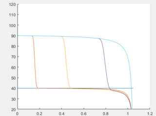
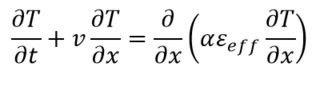
I could manage to build a numeric model for a sensible stratified storage tank by means of solving the convection-diffusion equation (1D) by use of Crank-Nicolson scheme.  I try to implement a mixing effect that is changing in a hyperbolic decaying form from the top of the tank (inlet is here) to the bottom. In the above equation, eps_eff is this mixing effect. The details can be found here: Zurigat et al - Stratified thermal storage tank inlet mixing characterization. Please see the Case 0, 1, and 2 under the section %% Inlet Mixing in the Matlab code given below. For Case 1 - No mixing effect included so a constant thermal diffusivity through the tank height, here is the result (simulation results are solid lines compared with the experimental result shown with circles): 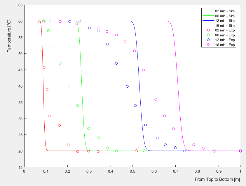 When Case 0 is active, the thermal diffusivity is replaced from constant to a decaying form through the tank height via multiplication with eps_eff in the code, the results become weird: 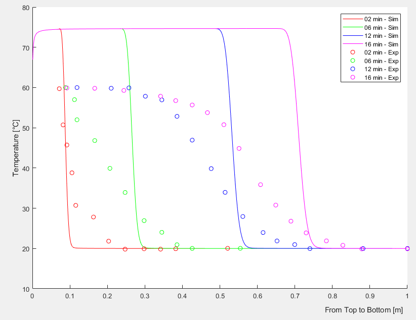 If Case 2, the thermal diffusivity is magnified up to a level up at a constant rate at all tank levels, the temperature does not increase above the inlet temperature but Case 0 all the time results in abnormal temperature increase. Would you please check my codes and/or explain to me why this abnormal temperature increase happens (stability, oscillation,... issues?)? Shall I try upwind or any other scheme in my solution considering the inlet mixing effect? Or any other suggestions? Here is the Matlab code: Code:
function [T,dh,dt] = CDR_CrankNicolson_Exp_InletMixing(t_final,n)
%% 1D Convection-Diffusion-Reaction (CDR) equation - Crank-Nicolson scheme
%   solves a d2u/dx2 + b du/dx + c u = du/dt

%% References
% pg. 28 - http://www.ehu.eus/aitor/irakas/fin/apuntes/pde.pdf
% pg. 03 - https://www.sfu.ca/~rjones/bus864/notes/notes2.pdf
% http://nptel.ac.in/courses/111107063/24

tStart = tic; % Measuring computational time

%% INPUT
% t_final   : overall simulation time [s]
% n         : Node number [-]

%% Tank Dimensions
h_tank=1;       % [m]       Tank height
d_tank=0.58; 	% [m]       Tank diameter
vFR=11.75;    	% [l/min]   Volumetric Flow Rate
v=((vFR*0.001)/60)/((pi*d_tank^2)/4);    % [m/s]     Water velocity

dh=h_tank/n;   	% [m] mesh size

dt=1;         	% [s] time step
maxk=round(t_final/dt,0);    % Number of time steps

% Constant CDR coefficients | a d2u/dx2 + b du/dx + c u = du/dt
a_const=0.15e-6; 	% [m2/s]Thermal diffusivity
b=-v;                        % Water velocity
c=0;                         %!!! Coefficient for heat loss calculation

%% Inlet Mixing - Decreasing hyperbolic function through tank height
eps_in=2;             % Inlet mixing magnification on diffusion
A_hyp=(eps_in-1)/(1-1/n);
B_hyp=eps_in-A_hyp;

Nsl=1:1:n;

eps_eff=A_hyp./Nsl+B_hyp;

a=a_const.*eps_eff;         % Case 0
% a=ones(n,1)*a_const;      % Case 1
% a=ones(n,1)*a_const*20;	% Case 2

%% Initial condition - Tank water at 20 degC
T=zeros(n,maxk);

T(:,1)=20;

%% Boundary Condition - Inlet temperature at 60 degC
T(1,:)=60;

%% Formation of Tridiagonal Matrices
%   Tridiagonal Matrix @Left-hand side
subL(1:n-1)=-(2*dt*a(1:n-1)-dt*dh*b);         	% Sub diagonal - Coefficient of u_i-1,n+1
maiL(1:n-0)=4*dh^2+4*dt*a-2*dh^2*dt*c;          % Main diagonal - Coefficient of u_i,n+1
supL(1:n-1)=-(2*dt*a(1:n-1)+dt*dh*b);         	% Super diagonal - Coefficient of u_i+1,n+1
tdmL=diag(maiL,0)+diag(subL,-1)+diag(supL,1);
%   Tridiagonal Matrix @Right-hand side
subR(1:n-1)=2*dt*a(1:n-1)-dt*dh*b;            	% Sub diagonal - Coefficient of u_i-1,n
maiR(1:n-0)=4*dh^2-4*dt*a-2*dh^2*dt*c;          % Main diagonal - Coefficient of u_i,n
supR(1:n-1)=2*dt*a(1:n-1)+dt*dh*b;           	% Super diagonal - Coefficient of u_i+1,n
tdmR=diag(maiR,0)+diag(subR,-1)+diag(supR,1);

%% Boundary Condition - Matrices
tdmL(1,1)=1; tdmL(1,2)=0;
tdmL(end,end-1)=0; tdmL(end,end)=1;

tdmR(1,1)=1; tdmR(1,2)=0;
tdmR(end,end-1)=1; tdmR(end,end)=0;

MMtr=tdmL\tdmR;

%% Solution - System of Equations
for j=2:maxk % Time Loop
Tpre=T(:,j-1);

T(:,j)=MMtr*Tpre;

if T(end,j)>=89.9
    T(:,j+1:end)=[];
    finishedat=j*dt;
    ChargingTime=sprintf('Charging time is %f [s]', finishedat)
    tElapsed = toc(tStart);
    SimulationTime=sprintf('Simulation time is %f [s]',tElapsed)
    return
end
end

end
|
|

|

|
|
|
July 24, 2018, 20:51
|
|
#2 |
|
Senior Member
Arjun
Join Date: Mar 2009
Location: Nurenberg, Germany
Posts: 1,272
Rep Power: 34 |
Based on the graphs, your diffusion term is creating a source that should not be there. If i were you i will just set the diffusion term to 0 in the cell connected to boundary and run it.
|
|
|
|
|
|
|
July 25, 2018, 03:31
|
|
#3 |
|
Senior Member
Filippo Maria Denaro
Join Date: Jul 2010
Posts: 6,768
Rep Power: 71 |
I see a poor accordance also in the constant thermal diffusivity case...
However, I haven't see the code but if you manage the eps_eff in the Crank-Nicolson scheme have you correctly considered the effect in the time-variying case? The matrix will change at each time step. Then, how do you discretize the spatial derivatives? |
|
|
|
|
|
|
July 25, 2018, 03:35
|
|
#4 | |
|
Member
Khan
Join Date: Jul 2018
Posts: 45
Rep Power: 7 |
Quote:
|
||
|
|
|
||
|
July 25, 2018, 03:45
|
|
#5 | |
|
Member
Khan
Join Date: Jul 2018
Posts: 45
Rep Power: 7 |
Quote:
Coefficients of approximated temperatures in the Crank-Nicolson scheme applied stay same with time so I calculate it once at the beginning (a fixed matrix). Do you think the problem is this? |
||
|
|
|
||
|
July 25, 2018, 03:56
|
|
#6 | |
|
Senior Member
Filippo Maria Denaro
Join Date: Jul 2010
Posts: 6,768
Rep Power: 71 |
Quote:
Therefore the coefficients of the matrix are time-dependent not constant |
||
|
|
|
||
|
July 25, 2018, 04:11
|
|
#7 | |
|
Member
Khan
Join Date: Jul 2018
Posts: 45
Rep Power: 7 |
Quote:
|
||
|
|
|
||
|
July 25, 2018, 04:40
|
|
#8 | |
|
Senior Member
Filippo Maria Denaro
Join Date: Jul 2010
Posts: 6,768
Rep Power: 71 |
Quote:
But are you including in the CN integration also the convection part?? Have you checked that a purely explicit FTCS works fine? Increasing the eps_eff greater to 1 you should see exactly the opposite effect, check also the correct sign in the coefficients, what you het is a sort of anti-diffusion. |
||
|
|
|
||
|
July 25, 2018, 05:12
|
|
#9 | |||
|
Member
Khan
Join Date: Jul 2018
Posts: 45
Rep Power: 7 |
Quote:
Quote:
Quote:
Thank you. |
||||
|
|
|
||||
|
July 25, 2018, 05:23
|
|
#10 |
|
Senior Member
Filippo Maria Denaro
Join Date: Jul 2010
Posts: 6,768
Rep Power: 71 |
As you are not experienced, start solving the explicit first order integration in time. Use central second order formula for the space derivatives.
At high values of eps_eff the numerical stability constraint is mainly based on dt*diff_coef/h^2<0.5 For convection dominated case you need a fine grid to avoid numerical oscillations |
|
|
|
|
|
|
July 25, 2018, 05:27
|
|
#11 | |
|
Member
Khan
Join Date: Jul 2018
Posts: 45
Rep Power: 7 |
Quote:
|
||
|
|
|
||
|
July 25, 2018, 08:35
|
|
#12 | |
|
Member
Khan
Join Date: Jul 2018
Posts: 45
Rep Power: 7 |
Quote:
|
||
|
|
|
||
|
July 25, 2018, 10:03
|
|
#13 | |
|
Senior Member
Filippo Maria Denaro
Join Date: Jul 2010
Posts: 6,768
Rep Power: 71 |
Quote:
|
||
|
|
|
||
|
July 26, 2018, 03:18
|
|
#14 | |
|
Member
Khan
Join Date: Jul 2018
Posts: 45
Rep Power: 7 |
Quote:
 The boundary condition at the right/bottom is dT/dt=0. |
||
|
|
|
||
|
July 26, 2018, 03:28
|
|
#15 |
|
Senior Member
Filippo Maria Denaro
Join Date: Jul 2010
Posts: 6,768
Rep Power: 71 |
Therefore, if I am right this problem has a thermal coefficient that increases going to the right of the diagram.
Just as a test, could you use the same law for eps_eff but changing only the sign so to decrease it? |
|
|
|
|
|
|
July 26, 2018, 04:48
|
|
#16 | |
|
Member
Khan
Join Date: Jul 2018
Posts: 45
Rep Power: 7 |
Quote:
|
||
|
|
|
||
|
July 26, 2018, 05:07
|
|
#17 |
|
Senior Member
Filippo Maria Denaro
Join Date: Jul 2010
Posts: 6,768
Rep Power: 71 |
The case now shows a diminishing temperature, right? So, it seems that the numerical solution describes opposite physical behaviors.
|
|
|
|
|
|
|
July 26, 2018, 08:20
|
|
#18 | |
|
Member
Khan
Join Date: Jul 2018
Posts: 45
Rep Power: 7 |
Quote:
|
||
|
|
|
||
|
July 26, 2018, 11:56
|
|
#19 | |
|
Senior Member
Filippo Maria Denaro
Join Date: Jul 2010
Posts: 6,768
Rep Power: 71 |
Quote:
Could you post your Matlab code for the simple FTCS case? I want try to have a check |
||
|
|
|
||
|
July 27, 2018, 03:44
|
|
#20 | |
|
Member
Khan
Join Date: Jul 2018
Posts: 45
Rep Power: 7 |
Quote:
 Now I focus on deriving the derivative approximation as to space dependent (x)  _eff _eff
|
||
|
|
|
||
|
|
|
 Similar Threads
|
||||
| Thread | Thread Starter | Forum | Replies | Last Post |
| The udf.h headers are unable to open- in VISUAL STUDIO 13 | sanjeetlimbu | Fluent UDF and Scheme Programming | 4 | May 2, 2016 05:38 |
| CFX Simple valve model, inlet and outlet conditions | 749604 | CFX | 24 | August 11, 2014 18:51 |
| Water subcooled boiling | Attesz | CFX | 7 | January 5, 2013 03:32 |
| convergence problem of the SST and RNG k-e model for mixing tank | ziyan7 | FLUENT | 0 | March 8, 2011 06:13 |
| How to model a rack of the inlet? | silvia_petkova | Main CFD Forum | 0 | March 17, 2010 06:08 |

 Linear Mode


