|
|
|
[Sponsors] | ||||
 October 9, 2018, 08:10
|
|
#1 |
|
Member
Khan
Join Date: Jul 2018
Posts: 45
Rep Power: 7  |
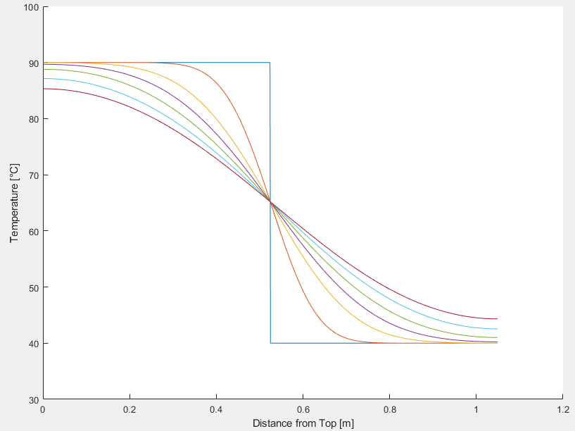
I try to model pure diffusion case, considered with solving of the one-dimensional convection-diffusion equation (considering no flow, v=0 so no convection but only diffusion!). The Matlab code is given below. Accordingly, the initial condition is with 'the top water mass of the tank is at 90 °C while the bottom water mass of the tank is at 40 °C' fifty-fifty. You can see the temperature profile changing through time, below (you can see that stratification expands with time):
 The problem is that when I calculate the energy content/enthalpy through the tank height at each time step; I found that the overall tank enthalpy increases through time by only the diffusion effect. The energy content shall stay at the same level through time since there is only diffusion (no heat loss or gain considered). The calculation procedure is as the sum of all node enthalpies (each node enthalpy calculated by node mass x specific enthalpy of the node temperature) at each time step. Would you please tell me why this energy content (enthalpy) increase occurs with time? Can the reason be the finite difference method (Shall I accept such error, the enthalpy increase, due to numerical matters?)?  Code:
function [T,H] = CDR_FTCS_Diffusion(t_final,n)
%% 1D Convection-Diffusion-Reaction (CDR) equation - (Forward-Time Central-Space)
%   solves a d2u/dx2 + b du/dx + c u = du/dt

%% INPUT
% t_final   : final time [s]
% n         : Node number [-]

%% OUTPUT
% T         : Temperature Matrix [degC]
% H         : Enthalpy Matrix [kJ]

if mod(n,2)==0 % Checkinf if node number is even or not!
    error('Node number - n - must be odd number - Check function input!')
end

%% INPUT
% Tank Dimensions
height=1.05;                % [m]       Tank height
diameter=0.45;              % [m]       Tank diameter
% v=5.2397e-4;             	% [m/s]     Water velocity
dx=height/n;                % [m]       mesh size
dt=1;                       % [s]       time step
maxk=round(t_final/dt,0); 	% Number of time steps

% Constant CDR coefficients | a d2u/dx2 + b du/dx + c u = du/dt
% a_const=0.15e-6;        	% [m2/s]Thermal diffusivity
b=0;%-v;                 	% [m/s] Water velocity
% c=0;                   	%!!! Coefficient for heat loss calculation


%% Initial condition
T=zeros(n+1,maxk);

% Case Half 90 degC Half 40 degC
T(1:(n+1)/2,1)=90;
T((n+1)/2+1:end,1)=40;

%% Fasten Your Seat Belts - Calculation of Temperature Profile at each time step

for j=2:maxk    % Time Loop
    Tpre=T(:,j-1);
    a(:,1)=-2.16308E-12.*Tpre.^2 + 5.67273E-10.*Tpre + 1.32439E-07; % [m2/s] Thermal diffusivity

    for i=2:n   % Space Loop
         T(i,j)=Tpre(i-1)*(-a(i+1)*dt/(4*dx^2)+a(i)*dt/dx^2+a(i-1)*dt/(4*dx^2)-b*dt/(2*dx))...
             +Tpre(i)*(1-2*a(i)/(dx^2)*dt)...
             +Tpre(i+1)*((a(i+1)-a(i-1))/(4*dx^2)+a(i)/(dx^2)+b/(2*dx))*dt;
    end

    T(n+1,j)=T(n,j); % Neumann boundary condition with backward Euler
    T(1,j)=T(2,j);

end

%% Calculate Energy Content for each time step
Tt=T;
% Tt(1,:)=[];
% Tt(end,:)=[];
rhoNode=-3.16677E-03.*Tt.^2 - 1.22228E-01.*Tt + 1.00199E+03;	% [kg/m3] Density
hlTNode= 4.18601E+00.*Tt + 1.32103E-01;                         % [kJ/kg] Specific Enthalpy

H_node=(pi*diameter^2/4)*dx.*rhoNode.*hlTNode;                  % [kJ] Enthalpy of each Node

H=sum(H_node);                                                  % [kJ] Total enthalpy at each time step
end
|
|

|

|
|
|
October 9, 2018, 10:59
|
|
#2 |
|
Senior Member
Filippo Maria Denaro
Join Date: Jul 2010
Posts: 6,768
Rep Power: 71 |
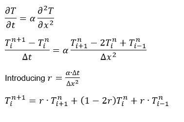
I do not consider the matlab code now but start the question showing all the equations of your model that you want to solve. Describe the PDE and the discretization.
|
|
|
|
|
|
|
October 10, 2018, 06:27
|
|
#3 | |
|
Member
Khan
Join Date: Jul 2018
Posts: 45
Rep Power: 7 |
Quote:

|
||
|
|
|
||
|
October 10, 2018, 10:19
|
|
#4 |
|
Senior Member
Filippo Maria Denaro
Join Date: Jul 2010
Posts: 6,768
Rep Power: 71 |
Why do you discretize this way the spatial derivative?
It is simply (uniform mesh) (T(i-1)-2*T(i)+T(i+1))/h^2 |
|
|
|
|
|
|
October 10, 2018, 11:05
|
|
#5 | |
|
Member
Khan
Join Date: Jul 2018
Posts: 45
Rep Power: 7 |
Quote:
I carried out the same simulation with Crank-Nicolson scheme (this time no mixing characterization so alpha is constant). Still, I have this increase even with Crank-Nicolson. I need to indicate that the increase ratio at pure diffusion case (both by Crank-Nicolson and FTCS) is at around 0.6% (after some reasonably large time). Is this increase reasonable when using finite difference methods? |
||
|
|
|
||
|
October 10, 2018, 11:16
|
|
#6 | |
|
Senior Member
Filippo Maria Denaro
Join Date: Jul 2010
Posts: 6,768
Rep Power: 71 |
Quote:
well, the PDE you wrote is not congruent to what you are doing.... If alpha is variable, you wrote a wrong PDE since you should write d/dx(alpha(x,t)*dT/dx) A general convection-diffusion equation would write in divergence form as dT/dt + d/dx (u*T - alpha(x,t)*dT/dx)=0 If you discretize on a compact stencil your formula is over 2h not over 4h |
||
|
|
|
||
|
October 10, 2018, 11:57
|
|
#7 | |
|
Member
Khan
Join Date: Jul 2018
Posts: 45
Rep Power: 7 |
Quote:
 and the relative error (still there is this increase, killing me  ): ): Code:
function [T,H] = CDR_FTCS_Simple_Diffusion(t_final,n)
%% 1D Convection-Diffusion-Reaction (CDR) equation - (Forward-Time Central-Space)
%   solves a d2u/dx2 + b du/dx + c u = du/dt

tStart = tic;

%% INPUT
% Tank Dimensions
height=1.05;                % [m]       Tank height
diameter=0.45;              % [m]       Tank diameter
% v=5.2397e-4;             	% [m/s]     Water velocity
dx=height/n;                % [m]       mesh size
dt=1;                       % [s]       time step
maxk=round(t_final/dt,0); 	% Number of time steps

% Constant CDR coefficients | a d2u/dx2 + b du/dx + c u = du/dt
a=0.15e-6;            % [m2/s]Thermal diffusivity
% b=0;%-v;                       % [m/s] Water velocity
% c=0;                        %!!! Coefficient for heat loss calculation

r=a*dt/(dx^2);

%% Initial condition - Tank water at 40 ?C
T=zeros(n+1,maxk);

% Case Half 90 degC Half 40 degC
T(1:(n+1)/2,1)=90;
T((n+1)/2+1:end,1)=40;

%% Fasten Your Seat Belts

for j=2:maxk % Time Loop
    Tpre=T(:,j-1);

    for i=2:n  % Space Loop
         T(i,j)=r*Tpre(i-1)+(1-2*r)*Tpre(i)+r*Tpre(i+1);
    end

    T(n+1,j)=T(n,j); % Neumann boundary condition with backward Euler
    T(1,j)=T(2,j);

end
tElapsed = toc(tStart);
SimulationTime=sprintf('Simulation time is %f [s]',tElapsed)

%% Calculate Energy Content for each time step
Tt=T;

% First Node
T_f=Tt(1,:);
rho_f=-3.16677E-03.*T_f.^2 - 1.22228E-01.*T_f + 1.00199E+03;	% [kg/m3] Density
hlT_f= 4.18601E+00.*T_f + 1.32103E-01;                      	% [kJ/kg] Specific Enthalpy
H_f=((pi*diameter^2/4)*dx.*rho_f.*hlT_f)./2;

% End Node
T_e=Tt(end,:);
rho_e=-3.16677E-03.*T_e.^2 - 1.22228E-01.*T_e + 1.00199E+03;	% [kg/m3] Density
hlT_e= 4.18601E+00.*T_e + 1.32103E-01;                          % [kJ/kg] Specific Enthalpy
H_e=((pi*diameter^2/4)*dx.*rho_e.*hlT_e)./2;

% Inner nodes
Tt(1,:)=[];
Tt(end,:)=[];

rhoNode=-3.16677E-03.*Tt.^2 - 1.22228E-01.*Tt + 1.00199E+03;    % [kg/m3] Density
hlTNode= 4.18601E+00.*Tt + 1.32103E-01;                         % [kJ/kg] Specific Enthalpy

H_node=(pi*diameter^2/4)*dx.*rhoNode.*hlTNode;                  % [kJ] Enthalpy of each Node

H=sum(H_node)+H_e+H_f;                                      	% [kJ] Total enthalpy at each time step
end
|
||
|
|
|
||
|
October 10, 2018, 12:37
|
|
#8 |
|
Member
Join Date: Dec 2012
Posts: 92
Rep Power: 13 |
It seems that you change the density with temperature.
Neither your PDE nor your energy integration is taking that into account. |
|
|
|
|
|
|
October 10, 2018, 12:45
|
|
#9 |
|
Senior Member
Filippo Maria Denaro
Join Date: Jul 2010
Posts: 6,768
Rep Power: 71 |
How do you compute the curve? Be careful, your equation describes a pure diffusion problem but, depending on the BCs., you could be prescribing an entering heat flux!
What are exactly your BCs.? |
|
|
|
|
|
|
October 11, 2018, 04:13
|
|
#10 | |
|
Member
Khan
Join Date: Jul 2018
Posts: 45
Rep Power: 7 |
Quote:
|
||
|
|
|
||
|
October 11, 2018, 04:15
|
|
#11 | |
|
Member
Khan
Join Date: Jul 2018
Posts: 45
Rep Power: 7 |
Quote:
Code:
    T(n+1,j)=T(n,j); % Neumann boundary condition with backward Euler
    T(1,j)=T(2,j);
|
||
|
|
|
||
|
October 11, 2018, 04:35
|
|
#12 | |
|
Senior Member
Filippo Maria Denaro
Join Date: Jul 2010
Posts: 6,768
Rep Power: 71 |
Quote:
Compute the integral of the temperature over the domain |
||
|
|
|
||
|
October 11, 2018, 05:07
|
|
#13 | |
|
Member
Khan
Join Date: Jul 2018
Posts: 45
Rep Power: 7 |
Quote:
(ii) and (iii) Can you please give more details about these points? I didn't get the idea. |
||
|
|
|
||
|
October 11, 2018, 06:52
|
|
#14 | |
|
Senior Member
Filippo Maria Denaro
Join Date: Jul 2010
Posts: 6,768
Rep Power: 71 |
Quote:
Let us start first by a theoretical result: the equation can be integrated over the total volume and can be rewritten as d/dt Int[V] T dx = alpha [ dT/dx|BC_right -dT/dx|BC_left] = 0 Therefore the solution must ensure Int[V] T dx= constant, being such constant equal to that at the initial condition. If you adopt a FV method, the equation above can be used to define the flux function alpha*dT/dx on each section. The "telescopic" property ensures that, numerically, the temperature is conserved, depending only on the values of the flux at the boundaries. Therefore, the numerical check requires only to compute the difference between Int[V] T dx at any time and the value computed at t=0. Ideally such difference is zero, check if numerically is of the order of the adopted (single/double) precision. |
||
|
|
|
||
|
October 11, 2018, 09:51
|
|
#15 | |
|
Member
Khan
Join Date: Jul 2018
Posts: 45
Rep Power: 7 |
Quote:
|
||
|
|
|
||
 |
| Tags |
| convection-diffusion, enthalpy, finite difference, matlab, stratification |
|
|
 Similar Threads
|
||||
| Thread | Thread Starter | Forum | Replies | Last Post |
| How does the particles' velocity affect the energy balance equation of gas phase | sy2516 | OpenFOAM Running, Solving & CFD | 0 | April 10, 2017 15:05 |
| Energy balance in solid using chtMRSF | hcl734 | OpenFOAM Running, Solving & CFD | 11 | February 8, 2016 14:03 |
| Energy & Mass balance in RES file | Lindel | Phoenics | 2 | October 23, 2008 19:18 |
| Energy balance | Julie Polyakh | Siemens | 9 | July 7, 2004 04:00 |
| Why FVM for high-Re flows? | Zhong Lei | Main CFD Forum | 23 | May 14, 1999 13:22 |

 Linear Mode


