|
|
|
[Sponsors] | ||||
 December 2, 2010, 21:19
|
|
#1 |
|
New Member
Michael
Join Date: Nov 2010
Posts: 23
Rep Power: 15  |
I have gone through all of the tutorials and believe that I'm following the correct process, however I'm still having issues.
1. I define points and connect them using lines making sure to separate them into parts. The picture attached shows the geometry. All the red lines are under th part name "wall", the blue line under the part name "inlet", the green line under the part name "outlet", and finally the yellow line under "interior wall". 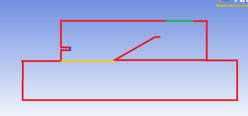 2. I then create two surfaces. The lower box is a solid while the upper portion is initially air. I create the surfaces by selecting the curves and keep the part names separate. The pink surface under the part name "solid" and the blue surface under the part name "air". 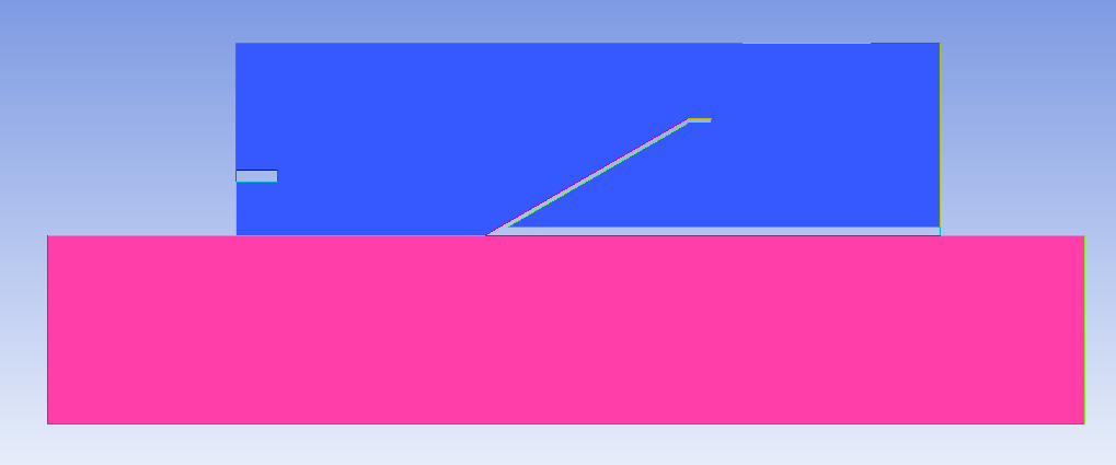 3. Then I block using 2D surface blocking and select my two surfaces. I use inherit part names this time. Then I pre mesh it and it is shown below. 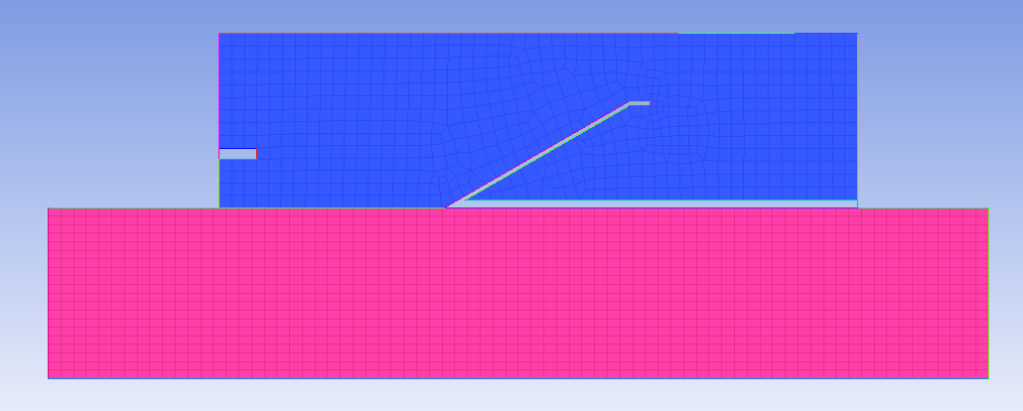 4. Finally I convert the premesh to an unstructured mesh and I get the result shown. It has combined my outlet and inlet into walls. 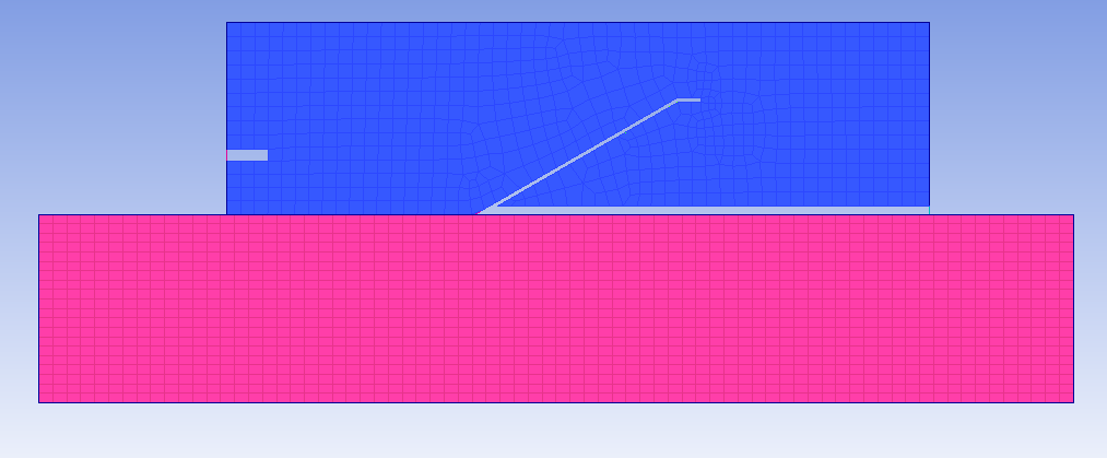 When I import the mesh into FLUENT there is no designation between where my outlet was and the wall. What causes my part names to disappear and become walls? Is this the correct process? Thanks, Michael |
|

|

|
|
|
December 3, 2010, 10:36
|
|
#2 |
|
Senior Member

Simon Pereira
Join Date: Mar 2009
Location: Ann Arbor, MI
Posts: 2,663
Blog Entries: 1
Rep Power: 47 |
In ICEM CFD, the element part names become the boundary conditions... I guess that has not happened.
1) The mesh edit fix for this simple model is to simply go to your mesh in ICEM CFD, turn off the shells and turn on the lines (from the mesh branch of the display tree). Zoom in on the outlet. In the model tree, right click on the Outlet part and choose "add to part". Since you have geometry displayed, it will default to selecting geometry. A selection toolbar will pop up, select the last ICON to change it to select mesh. Then box select the line elements along the outlet curve. Apply. These elements are now in the Outlet part and will be available in Fluent. 2) There may be a quicker mesh edit fix if you use the option under edit mesh => Repair Mesh => Associate Mesh. Then use the selection tool to "select all line elements". 3) The "best" fix, is probably at the blocking level. Go into the blocking tab => Associate => Edge to Curve. Zoom in and select the edge segment corresponding to the outlet. (At this point is is a single long edge with two edge splits to capture the ends of the outlet) Select the outlet curve. However, at least for my test case, there was an error. I will submit a defect. |
|
|
|
|
|
|
December 3, 2010, 11:02
|
|
#3 |
|
New Member
Michael
Join Date: Nov 2010
Posts: 23
Rep Power: 15 |
Thank you very much! Using option 1 I was able to export the mesh properly. I tried option 3 with no luck, but I may have been doing something wrong. Once again thank you for your help.
|
|
|
|
|
|
|
December 3, 2010, 11:16
|
|
#4 |
|
Senior Member
Simon Pereira
Join Date: Mar 2009
Location: Ann Arbor, MI
Posts: 2,663
Blog Entries: 1
Rep Power: 47 |
Actually, I did figure out 3. It had combined the curves into a composite curve. I had to break that up again (ungroup curves) and then associate...
I could also have added surface block splits. Simon ----------------------------------------- Please help guide development at ANSYS by filling in these surveys Public ANSYS ICEM CFD Users Survey This second one is more general (Gambit, TGrid and ANSYS Meshing users welcome)... CFD Online Users Survey |
|
|
|
|
|
|
December 6, 2010, 14:27
|
|
#5 |
|
New Member
Michael
Join Date: Nov 2010
Posts: 23
Rep Power: 15 |
Now I have a new error. It says:
"Warning: Inappropriate zone type (interior) for one-sided face zone 2. Changing to wall" This is the edge that I have labeled interior wall. How do I go about assigning this edge to both zones so that it may be considered interior? It is purely initial boundary between my solid zone and my gas zone. Thanks, Mike |
|
|
|
|
|
|
May 11, 2016, 11:49
|
|
#6 |
|
New Member
Join Date: Mar 2016
Posts: 4
Rep Power: 10 |
Hello Community,
I'm sorry for writing in this old thread but I have a similar problem. I created a 2D geometry and defined the curves and one surface to different parts. After that I meshed my 2D planar with blocking. Then I extruded the mesh by one layer axial (5°) and by a curve. The curve was produced before by rotating the profile. Extruding my mesh I need because I'm working with cfx later. So, now I have the extruded Mesh and my cfx doesn't recognize the defined parts. I think I have only defined the surfaces of the geometry and not the Mesh-surfaces. I searched for my problem in many tutorials but I couldn't find something. Can someone help me? Sometimes when I want to 'add to part' I can label single cells, but my Mesh is very fine -I think it would be very exhausting to label every cell. Moreover I don't think it's provided to do it in that way. It would be great to get help! Thanks in advance greets -smaru |
|
|
|
|
|
|
May 16, 2016, 14:26
|
|
#7 |
|
Member
B.H.
Join Date: Nov 2014
Location: PA, USA
Posts: 47
Rep Power: 11 |
Hi, so when you created the 2-D planer blocking, it was assigned to its own part, correct? The mesh should keep the same part association.
|
|
|
|
|
|
 |
|
|
 Similar Threads
|
||||
| Thread | Thread Starter | Forum | Replies | Last Post |
| 3D Hybrid Mesh Errors | DarrenC | ANSYS Meshing & Geometry | 11 | August 5, 2013 06:42 |
| engrid -> save as .stl with boundarie codes | Zymon | enGrid | 31 | August 29, 2011 13:40 |
| Mesh generation software is needed | H.Dou | Main CFD Forum | 12 | May 4, 2011 15:20 |
| icem hexa mesh parts pb | jaber | CFX | 5 | July 8, 2009 03:59 |
| [ICEM] icem hexa mesh parts pb | jaber | ANSYS Meshing & Geometry | 3 | July 5, 2009 06:23 |
 Linear Mode


