|
|
|
[Sponsors] | ||||
FFD shape deformation for 3D wing not changing the mesh |
 |
|
|
LinkBack | Thread Tools | Search this Thread | Display Modes |
 February 7, 2017, 09:40
|
|
#1 |
|
New Member
Laurence
Join Date: Mar 2016
Posts: 2
Rep Power: 0  |
I'm trying to do standalone mesh deformation with SU2 (since I am using my own optimization routines) on the ONERAM6 3D mesh.
I am using the mesh_ONERAM6_turb.su2 mesh from the steady oneram6 optimization rans test case as a starting mesh. I am using the FFD box from the inviscid oneram6 example, which I implement with the following lines in my config file: % -------------------- FREE-FORM DEFORMATION PARAMETERS -----------------------% FFD_TOLERANCE= 1E-10 % FFD_ITERATIONS= 500 % FFD_DEFINITION= (WING_BOX,-0.0403, 0, -0.04836,0.8463,0, -0.04836,1.209,1.2896, -0.04836,0.6851,1.2896, -0.04836,-0.0403,0, 0.04836,0.8463,0, 0.04836,1.209,1.2896, 0.04836,0.6851,1.2896, 0.04836) % FFD_DEGREE= (3, 2, 1) % FFD_CONTINUITY= 2ND_DERIVATIVE Running a mesh deformation with DV_KIND = FFD_SETTING works fine and produces the desired FFD control points. Now when I try to run the actual deformation, by adding the following lines in my config file: % ------------------------ GRID DEFORMATION PARAMETERS ------------------------% DV_KIND= FFD_CONTROL_POINT, FFD_CONTROL_POINT % DV_MARKER= ( wing ) % DV_PARAM= ( WING_BOX, 0, 0, 0, 0.0, 0.0, 1.0 ); ( WING_BOX, 0, 0, 1, 0.0, 0.0, 1.0 ) % DV_VALUE= 0.1, 0.1 % DEFINITION_DV= ( 7, 1.0 | wing | WING_BOX, 0, 0, 0, 0.0, 0.0, 1.0 ); ( 7, 1.0 | wing | WING_BOX, 0, 0, 1, 0.0, 0.0, 1.0 ) % VISUALIZE_DEFORMATION= YES The process seems to complete successfully, however when I look at the output mesh, and the ffd_boxes.dat output file shows no difference between the location of the control points. I believe I am following the steps outline in this thread FFD control point deformation, but it doesn't seem to be working. Any help would be much appreciated! The console output during the mesh deformation is given below: ------------------------ Physical Case Definition ----------------------- Input mesh file name: mesh_ONERAM6_turb_original.su2 ---------------------- Grid deformation parameters ---------------------- Grid deformation using a linear elasticity method. Design variables definition (markers <-> value <-> param): FFD (control point) <-> wing <-> 0.001 <-> ( WING_BOX, 0, 0, 0, 0, 0, 1 ) FFD (control point) <-> wing <-> 0.001 <-> ( WING_BOX, 0, 0, 1, 0, 0, 1 ) -------------------------- Output Information --------------------------- Output mesh file name: mesh_out.su2. A file will be created to visualize the deformation. Cell stiffness scaled by inverse of the cell volume. ------------------- Config File Boundary Information -------------------- Far-field boundary marker(s): farfield. Symmetry plane boundary marker(s): symmetry. Constant heat flux wall boundary marker(s): wing. ---------------------- Read Grid File Information ----------------------- Three dimensional problem. 96252 points before parallel partitioning. Performing linear partitioning of the grid nodes. 545438 interior elements before parallel partitioning. Calling the partitioning functions. Building the graph adjacency structure. Distributing elements across all ranks. 3 surface markers. 2802 boundary elements in index 0 (Marker = farfield). 16052 boundary elements in index 1 (Marker = symmetry). 2816 boundary elements in index 2 (Marker = wing). Calling ParMETIS... Finished partitioning using ParMETIS (24025 edge cuts). Communicating partition data and creating halo layers. 581834 interior elements including halo cells. 581834 tetrahedra. 109639 vertices including ghost points. Establishing MPI communication patterns. ----------------------- Preprocessing computations ---------------------- Setting local point connectivity. Checking the numerical grid orientation. Identify edges and vertices. Computing centers of gravity. Setting the bound control volume structure. Merging grid connectivity. Merging grid coordinates. Writing volume mesh file. Writing surface mesh file. Writing .su2 file. ------------------------- Surface grid deformation ---------------------- Performing the deformation of the surface grid. 1 Free Form Deformation boxes. 1 Free Form Deformation nested levels. FFD box tag: WING_BOX. FFD box level: 0. Degrees: 3, 2, 1. FFD Blending using Bezier Curves. Number of parent boxes: 0. Number of child boxes: 0. Corner points: 8. Control points: 24. Surface points: 1519. Writing a Paraview file of the FFD boxes. ----------------- FFD technique (parametric -> cartesian) --------------- Checking FFD box dimension. Checking FFD box intersections with the solid surfaces. The FFD planes j=0, intersect solid surfaces. SU2 is fixing the planes to maintain a continuous 2nd order derivative. Update cartesian coord | FFD box: WING_BOX. Max Diff: 1.53505e-10. Writing a Paraview file of the FFD boxes. ----------------------- Volumetric grid deformation --------------------- Performing the deformation of the volumetric grid. Computing volumes of the grid elements. Min. volume: 3.91157e-13, max. volume: 1.41456. # LU_SGS preconditioner. # FGMRES residual history # Residual tolerance target = 3.91157e-16 # Initial residual norm = 0.000362746 0 1 50 1.84268e-09 100 9.02009e-10 150 6.97651e-10 200 1.7469e-10 250 1.31106e-10 300 4.44597e-11 350 1.67551e-11 400 6.43674e-12 450 1.81654e-12 500 3.95255e-13 # FGMRES final (true) residual: # Iteration = 500: |res|/|res0| = 3.95255e-13. Computing volumes of the grid elements. Non-linear iter.: 1/2. Linear iter.: 500. Min. volume: 3.91157e-13. Error: 1.43377e-16. Computing volumes of the grid elements. Min. volume: 3.91157e-13, max. volume: 1.41456. # LU_SGS preconditioner. # FGMRES residual history # Residual tolerance target = 3.91157e-16 # Initial residual norm = 0.000362746 0 1 50 1.84269e-09 100 9.01976e-10 150 6.97636e-10 200 1.77482e-10 250 1.33931e-10 300 4.45252e-11 350 1.66251e-11 400 6.39568e-12 450 1.82168e-12 500 4.0082e-13 # FGMRES final (true) residual: VISUALIZE_DEFORMATION= YES │# Iteration = 500: |res|/|res0| = 4.0082e-13. Computing volumes of the grid elements. Non-linear iter.: 2/2. Linear iter.: 500. Min. volume: 3.91157e-13. Error: 1.45396e-16. ----------------------- Write deformed grid files ----------------------- Merging grid connectivity. Merging grid coordinates. Writing volume mesh file. Writing surface mesh file. Writing .su2 file. Adding any FFD information to the SU2 file. Completed in 77.826099 seconds on 8 cores. 19 │ ------------------------- Exit Success (SU2_DEF) ------------------------ |
|

|

|
|
|
February 13, 2017, 05:20
|
|
#2 |
|
Super Moderator
Tim Albring
Join Date: Sep 2015
Posts: 195
Rep Power: 10 |
Hi Laurence,
in the output is says: "The FFD planes j=0, intersect solid surfaces. SU2 is fixing the planes to maintain a continuous 2nd order derivative." Since both of your design variables are on the plane j=0, there will be no deformation. Tim |
|
|
|
|
|
|
February 15, 2017, 10:55
|
|
#3 |
|
New Member
Laurence
Join Date: Mar 2016
Posts: 2
Rep Power: 0 |
Tim,
That makes sense, I've got it working fine now, thanks. |
|
|
|
|
|
|
July 25, 2017, 21:56
|
|
#4 | |
|
New Member
Join Date: May 2017
Posts: 5
Rep Power: 8 |
Quote:
Im facing the same problem, when using DV_KIND= FFD_TWIST_ANGLE DV_PARAM= ( WING, -0.0403, 0, -0.04836, -0.0403, 0.0, 0.0 ) can you tell me how do you fix your problem? thanks a lot! best! |
||
|
|
|
||
|
November 5, 2017, 05:01
|
|
#5 | |
|
New Member
JAMES
Join Date: Dec 2016
Posts: 21
Rep Power: 9 |
Quote:
|
||
|
|
|
||
|
August 1, 2019, 15:17
|
|
#6 |
|
New Member
Angu Praveen
Join Date: May 2019
Posts: 14
Rep Power: 6 |
Dear all,
I know this is a long shot. I am trying to optimize the wing section of a BWB aircraft. I am currently facing a problem where my FFD is not interacting with the geometry. I am not aware of how to get over this. So basically I ran the SU2_DEF and generated the FFD and then set up a few control points(198 in my case) as design variables and then run SU2_CFD and SU2_CFD_AD after that. Once all the calculations are done, I wanted to do the sensitivity analysis before going forward with the optimization. Unfortunately, my FFD intersects the geometry and all the gradients are "Zero". I tried changing the FFD_CONTINUITY to 'NO_DERIVATIVE', '1ST_DERIVATIVE' and also 2ND_DERIVATIVE. But the results are the same. It would be really helpful if you can help me bypass this issue, I've attached a few pictures and the outputs for your reference. Looking forward to hearing from you. Kind regards Angu ----------------- FFD technique (parametric -> cartesian) --------------- Checking FFD box dimension. Checking FFD box intersections with the solid surfaces. The FFD planes i=0, i=10, intersect solid surfaces. SU2 is fixing the planes to maintain a continuous 2nd order derivative. Update cartesian coord | FFD box: WING. Max Diff: 0. Design variable (FFD_CONTROL_POINT) number 0. DRAG gradient : 0 ------------------------------------------------------------------------- 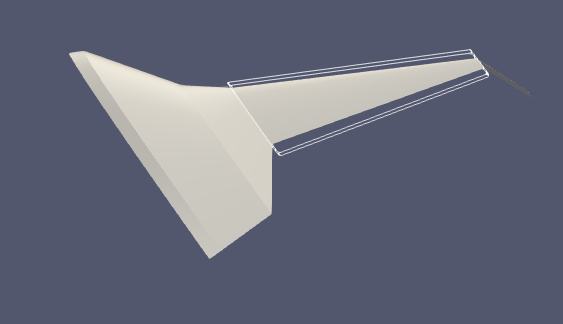
|
|
|
|
|
|
|
| Tags |
| 3d wing, ffd, mesh deformation, onera |
|
|
 Similar Threads
|
||||
| Thread | Thread Starter | Forum | Replies | Last Post |
| [ANSYS Meshing] 3d wing hex mesh | visigot | ANSYS Meshing & Geometry | 1 | August 24, 2016 02:02 |
| [snappyHexMesh] snappyHexMesh won't work - zeros everywhere! | sc298 | OpenFOAM Meshing & Mesh Conversion | 2 | March 27, 2011 21:11 |
| mesh missing after export in gambit | morteza08 | ANSYS Meshing & Geometry | 1 | July 26, 2010 01:10 |
| mesh missing after export in gambit | morteza08 | Main CFD Forum | 0 | July 23, 2010 02:19 |
| Convergence moving mesh | lr103476 | OpenFOAM Running, Solving & CFD | 30 | November 19, 2007 14:09 |

 Linear Mode


