|
|
|
[Sponsors] | ||||
Choosing Turbulence Model for transitionl flows |
|
|
LinkBack | Thread Tools | Search this Thread | Display Modes |
 May 27, 2015, 05:48
|
|
#1 |
|
New Member
Hannes
Join Date: Apr 2015
Posts: 3
Rep Power: 11  |
Hello guys,
I am currently working on a 3D flow simulation of an orifice for high pressure homogenization for my thesis. The orifice is part of a 2D2C µPIV (Particle Image Velocity) flow measurement system. Since the system cannot handle velocities above 100-150 m/s the Reynolds numbers only range from about 300-3000. This is clearly not fully turbulent. I understand that most turbulence models base on fully turbulent flows to be fully applicable. I am looking for the most accurate model for my case. So if you have any experience which model provides the best solutions please share it with me  Here are some more information: First of all I am using Fluent but since this is a question regarding turbulence models I hope it is okay to post it in the Main CFD Forum The goal of my investigation is to compare the limitations of both techniques CFD and PIV. Most CFD Users use the experimental results of PIV measurements to validate their simulations but I would like to do it both ways. The 2D2C µPIV measurement produces errors due to particles moving out of the 2D measurement plane. The movement in z-direction produces errors since PIV measurement compares two images and calculates the speed of the particles due to the change of position. Since my simulation should give an idea of this error it must be as accurate as it can be. There are 3D3C measurement techniques such as stereo PIV but it is not applicable (and affordable) to our problem. At the moment I am thinking about a 4 equ Transition SST or 7 equ Reynolds Stress model. Thank you for your input!!!! Hannes Last but not least some images of my orifice (results of a laminar calculation Re=230) First picture: View of the orifice from above (diameter of the canal = 0,2mm)   Second picture: Side view the orifice is build like this to be able to visualize the flow in the canal. The orifice is made from steel with acrylic glas on top to be accessible for the laser and camera Second picture: Side view the orifice is build like this to be able to visualize the flow in the canal. The orifice is made from steel with acrylic glas on top to be accessible for the laser and camera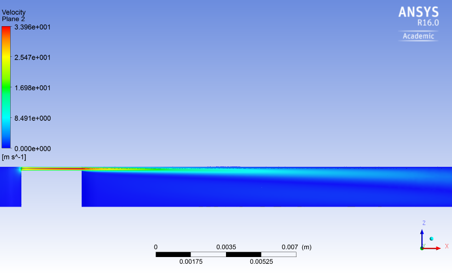
|
|

|

|
|
| Tags |
| orifice, piv, tranisitional flow, turbunce model |
|
|
 Similar Threads
|
||||
| Thread | Thread Starter | Forum | Replies | Last Post |
| Modified k-e turbulence model UDF | Travis | Fluent UDF and Scheme Programming | 7 | November 11, 2018 20:21 |
| An error has occurred in cfx5solve: | volo87 | CFX | 5 | June 14, 2013 17:44 |
| K - epsilon VS SST turbulence model | Maicol | Main CFD Forum | 0 | November 30, 2012 16:25 |
| What model of turbulence choose to study an external aerodynamics case | raffale | OpenFOAM | 0 | August 23, 2012 05:45 |
| Turbulence model for vortical flows | Dan Chambers | STAR-CCM+ | 0 | December 30, 2010 09:07 |


 Threaded Mode


